Building a 3D Printable Handwheel
Build a small handwheel with four spokes, a raised hub, and twelve finger grips. A hexagonal pocket holds a bolt head, so turning the wheel turns the bolt. The underside stays flat for printing.
The construction uses simple sketches: two circles for the rim, one rectangle for a spoke, and separate sketches for the hub and hardware. You will repeat the spoke around the center, then repeat a grip cut together with its fillet. Rounding that cut before patterning it gives the final top fillet a smooth outline to follow.
You can follow the whole tutorial in the workspace UI. The screenshots include the toolbar, History, and operation dialogs; the complete model is available at the end.
Before you start
Click + in the top bar and create handwheel.fluid.js. Use mm as the document unit. The screenshots use the light theme.
The main dimensions are:
| Feature | Size |
|---|---|
| Rim | Ø75 outside, Ø59 inside, 10 high |
| One spoke | 33.5 long × 8 wide × 5 high |
| Hub | Ø24 × 16 high |
| Bolt bore | Ø6.6, through all |
| Hex pocket | 10.4 across flats, 4.5 deep |
| Grip cut | Ø12, centered 42 from the wheel axis |
The hardware dimensions are a starting point for an M6 hex-head bolt. Check your bolt and printer's fit before making a batch.
A few controls you will use throughout:
- Ctrl+click adds to a selection. Rotate the view to reach edges on the far side.
- While sketching, typed sizes become dimensions. Use the constraint bar until the bottom pill reads Fully constrained.
- Click Finish Sketch, then choose a 3D operation from the toolbar.
- Apply commits a feature; Exit closes its dialog. You can double-click a History row to revisit its settings—the screenshots of those dialogs show the same inputs and previews.
- Right-click a History row and choose Rename. The short names below help you find the right feature when creating the patterns.
Step 1: Make the rim
Draw two concentric circles
Click Sketch, then pick the XY plane. Select Circle, click the origin, type 75, and press Enter. Draw a second circle at the same center with diameter 59.
Keep Infer while drawing enabled so snapping to the origin constrains the centers. If a circle can still move, select its center and the origin, then apply Coincident. Both diameters must be constrained, and the pill should read Fully constrained.
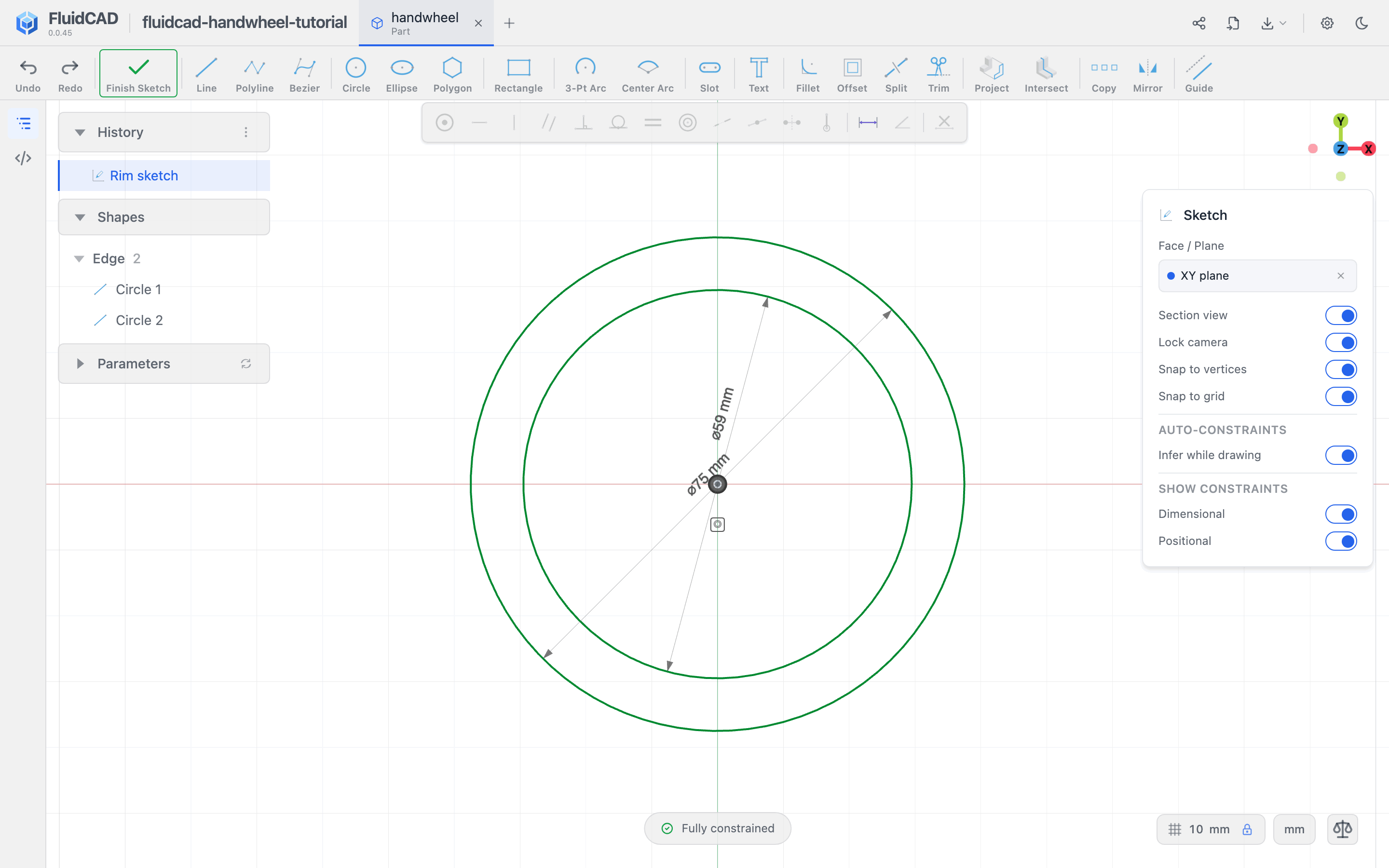
Rename the sketch Rim sketch.
Extrude the ring
Click Finish Sketch, then Extrude. Keep Add selected, set Distance to 10, and leave Drill holes on. The inner circle makes the opening; the preview should be a ring.
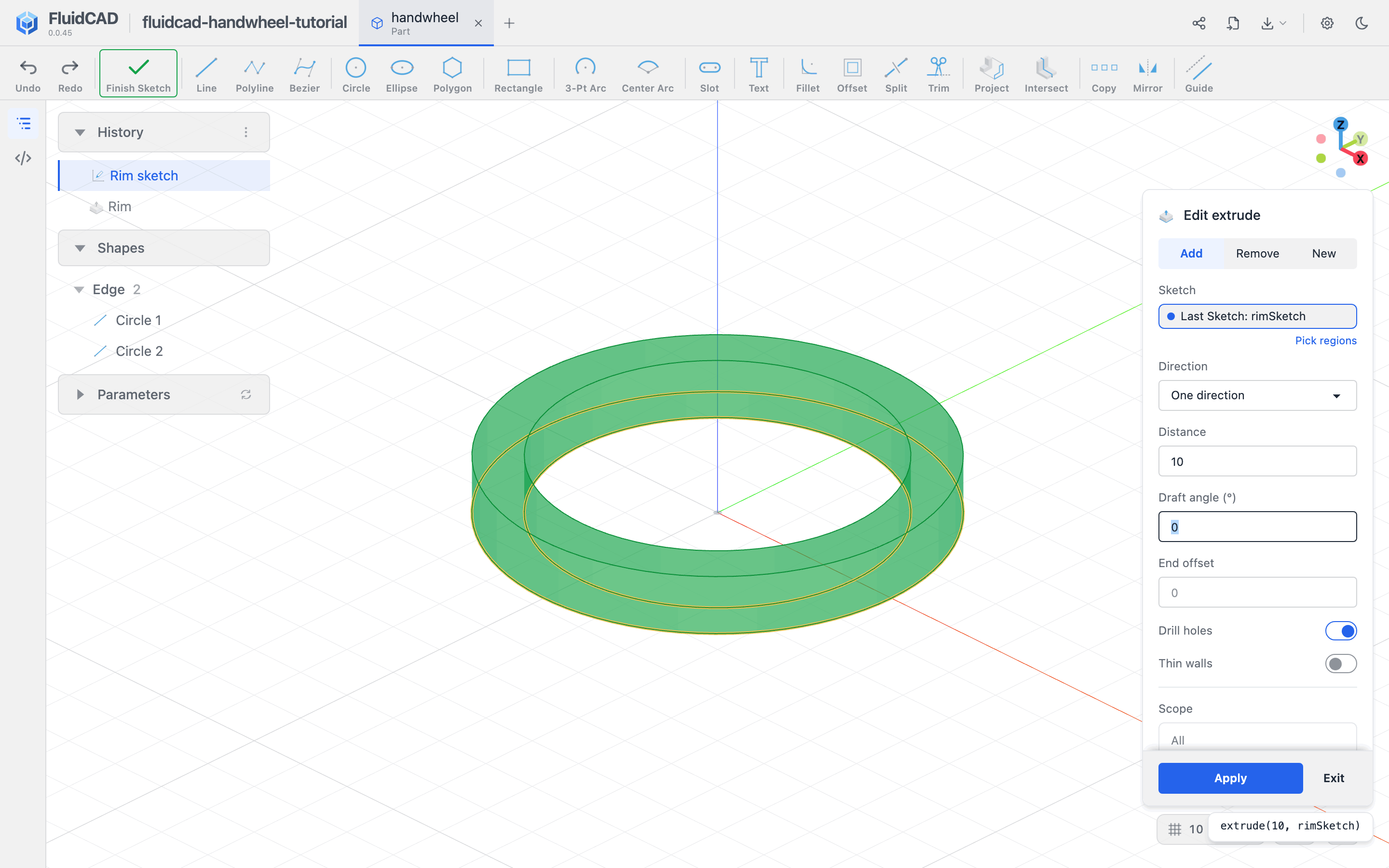
Click Apply and rename the feature Rim.
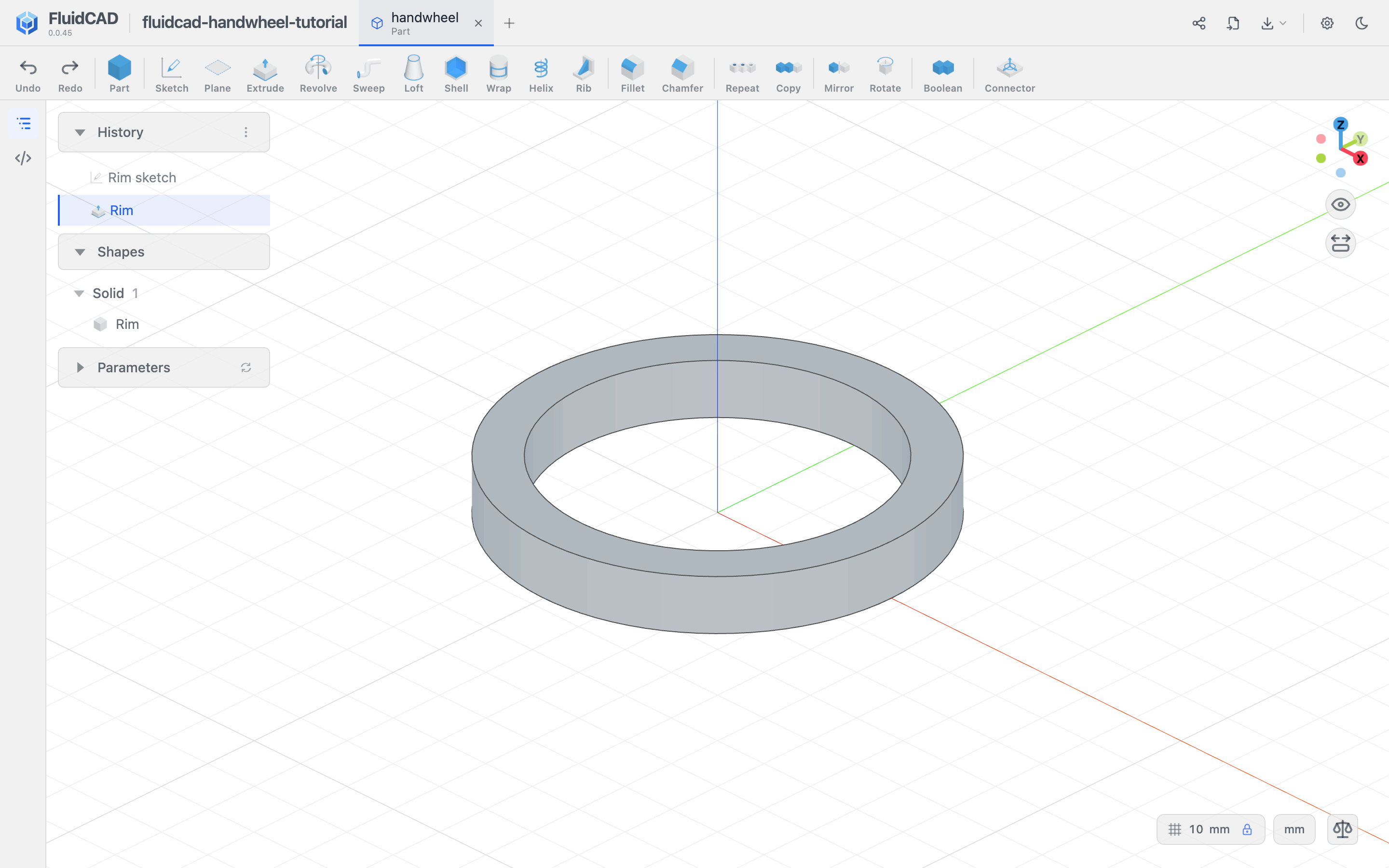
Step 2: Add one spoke and repeat it
Sketch a rectangle on XY
Start another sketch on the XY plane. This keeps the spoke's underside level with the rim's underside. The sketch's section view makes the rim appear as a flat reference.
Use Rectangle to draw from (0, -4) toward positive X. Enter a width of 33.5 and a height of 8. The left edge is centered on the origin; the right end extends halfway into the rim so the extrusion will fuse with it.
To place the first corner accurately, click the grid-spacing value at the bottom right and use a fixed spacing of 1 mm with Snap to grid enabled. Place the corner four grid intervals below the origin on the vertical axis. Select that corner and use Fix if its position is not already constrained. Keep the rectangle's typed dimensions and horizontal/vertical constraints.
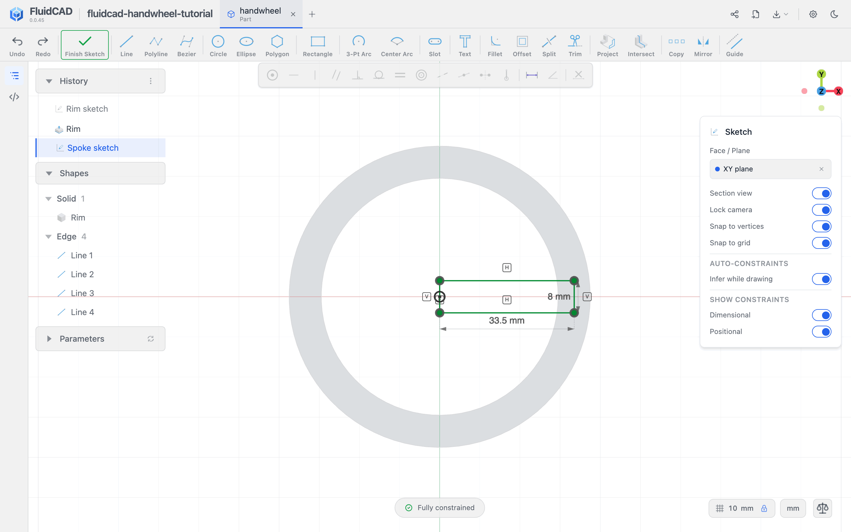
Name it Spoke sketch. Click Finish Sketch, then Extrude. Use Add, set Distance to 5, and check that the green preview meets the rim.
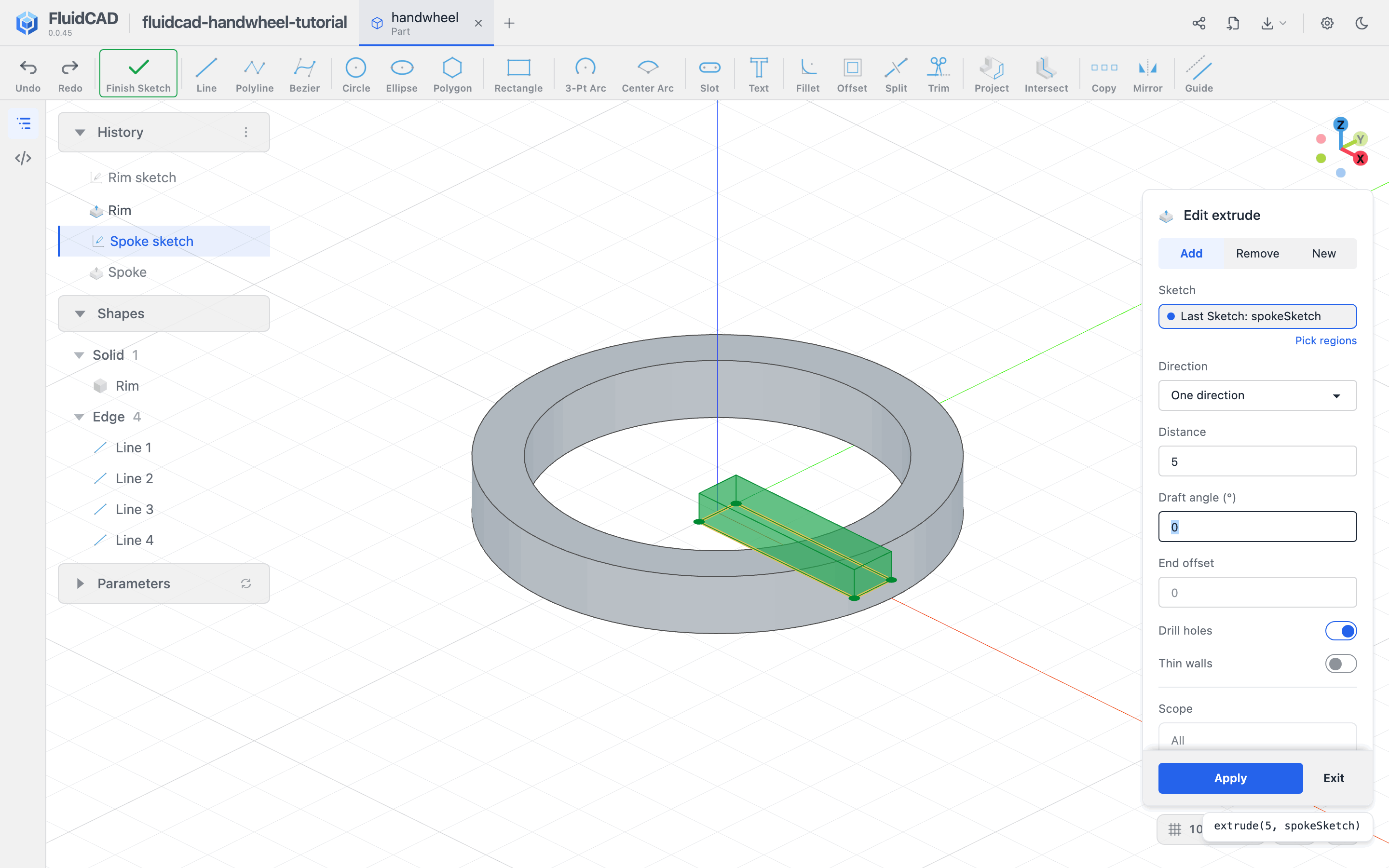
Click Apply and name the feature Spoke.
Repeat the spoke four times
Click Repeat and set Type to Circular. Click Spoke in History to put it in the Features slot. Use World Z axis, set Total Count to 4, and use a total angle of 360.
The count includes the first spoke: the preview adds three more at 90° intervals. Pick the Spoke extrusion, not its sketch or the entire solid.
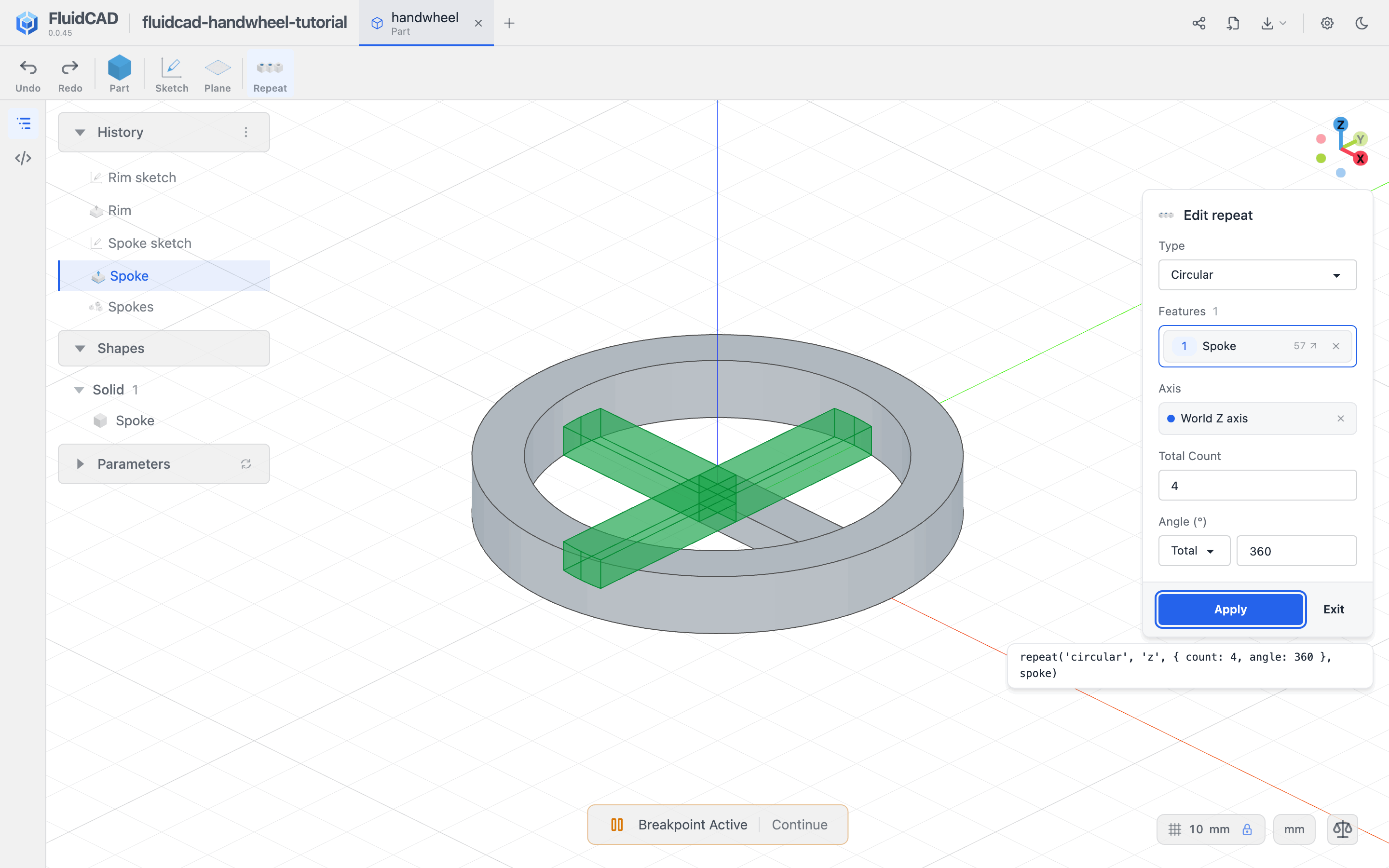
Click Apply and name the repeat Spokes.
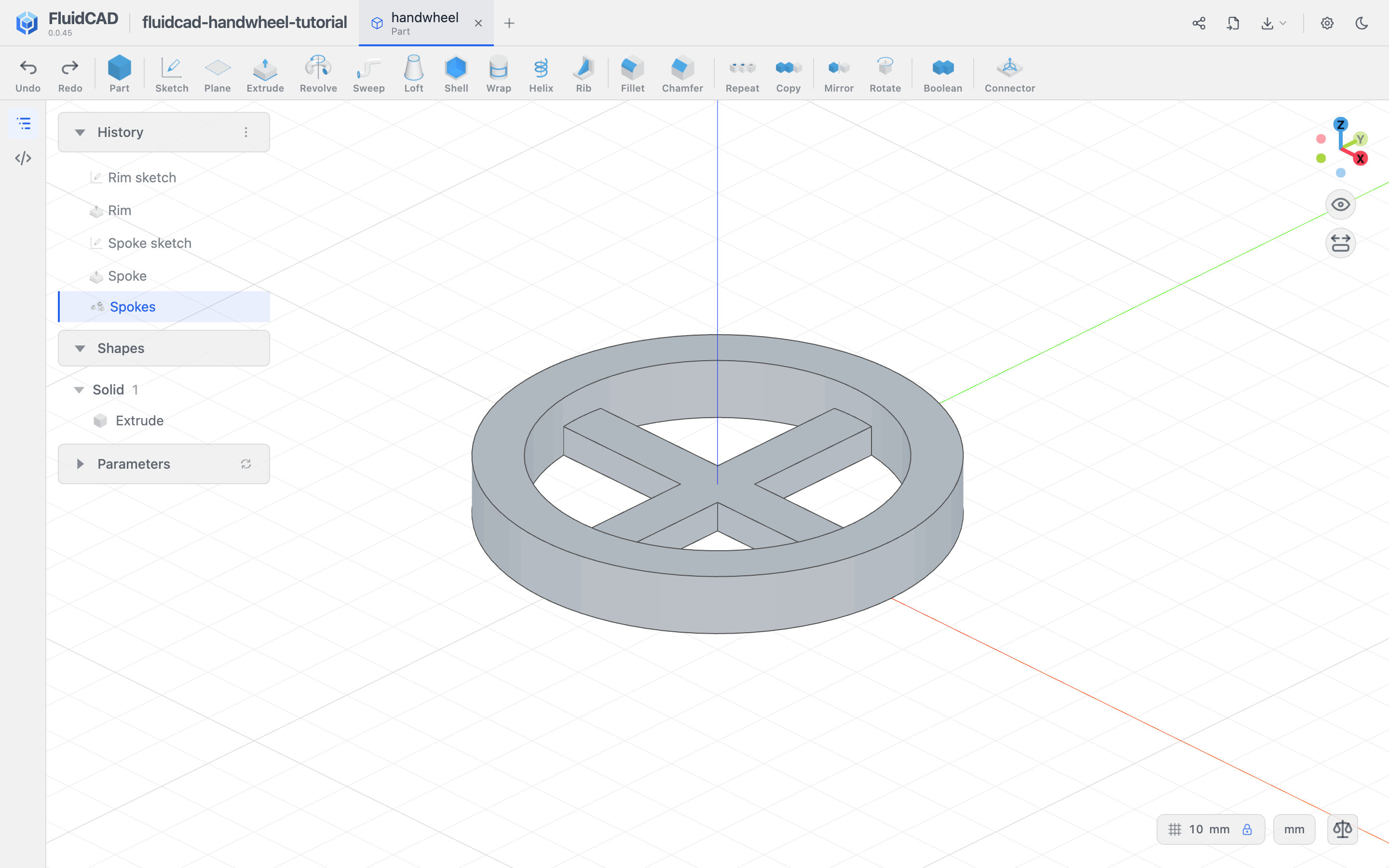
Step 3: Raise the hub
Start a new sketch on XY. Draw a circle centered on the origin with diameter 24. Constrain the center and diameter, and name the sketch Hub sketch.

Finish the sketch and extrude it 16 mm in Add mode. This is the hub's total height from the underside, not an extra 16 mm above the spokes.
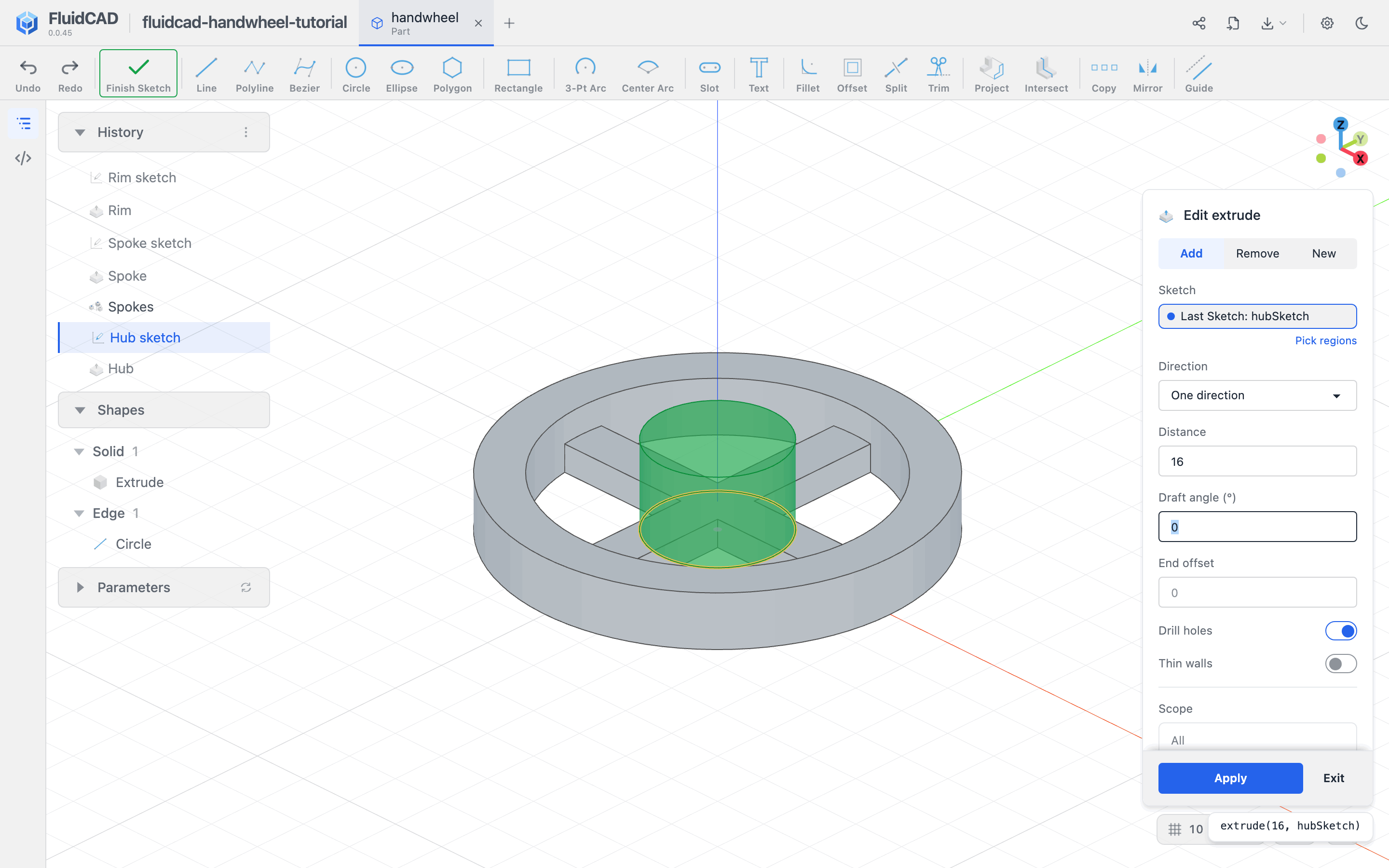
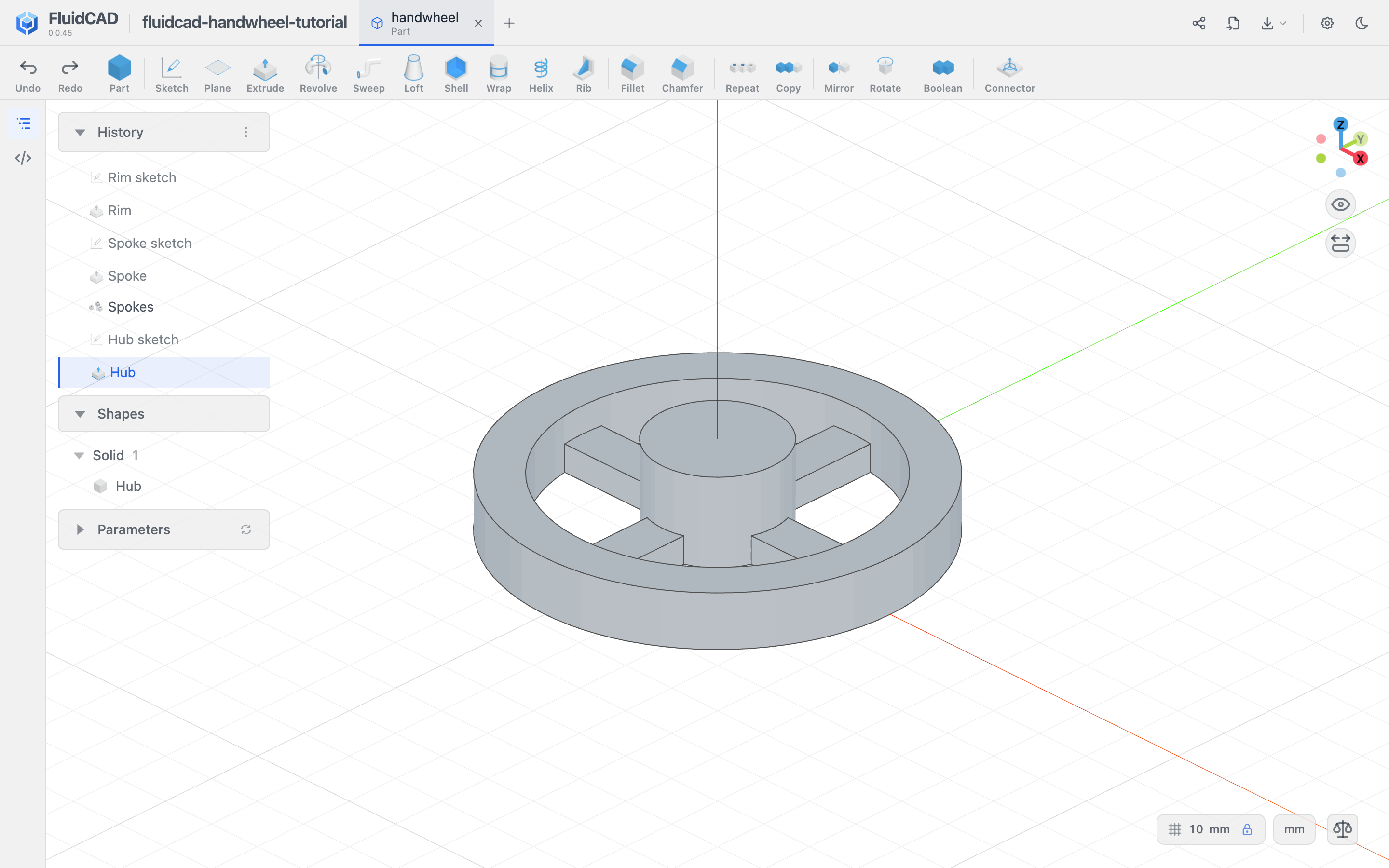
Apply and name it Hub. The circle fills the meeting point of the spokes and leaves four openings between the hub and rim.
Step 4: Cut the bolt bore
Reference the hub's center
Click Sketch and pick the hub's top face. Choose Project, select the hub's outer circular top edge, and apply the projection. Use Guide on the projected geometry so it acts as a reference without becoming a cutting profile.
Draw a circle approximately at its center and enter diameter 6.6. Select the new circle and the projected circle, then apply Concentric. This locates the bore from the hub itself, rather than assuming the face sketch's origin is at its center.

Name the sketch Bore sketch and finish it.
Remove through all
Open Extrude, select Remove, and switch on Through all. The cut runs down into the hub from its top face. The statement uses cut(...).
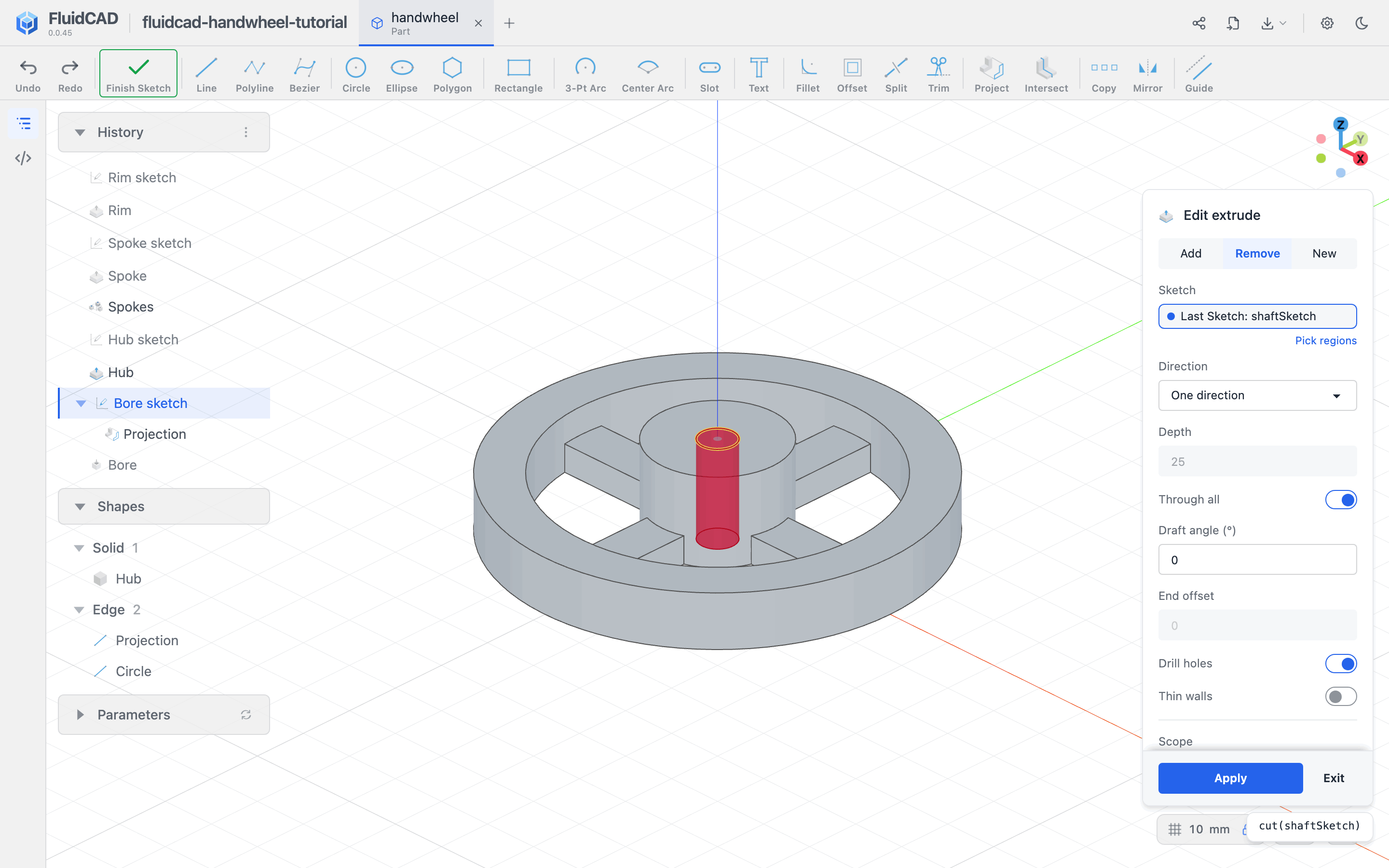
Apply and name the feature Bore.
Step 5: Make the hexagonal head pocket
Start another sketch on the hub's top face. Project its outer circular edge again and make the projection a Guide.
Choose Polygon and leave its mode on Circumscribed. Place its center at the center of the projected circle. Type 10.4 for the diameter and 6 for the side count, pressing Enter after each value. In this mode the diameter is measured across the flats.
The Polygon tool creates the guide circle and the relationships that keep the hexagon regular. If its center was not snapped to the reference, select its guide circle and the projected circle and apply Concentric. Select the upper side and apply Horizontal to fix the remaining rotation. The pill must read Fully constrained.
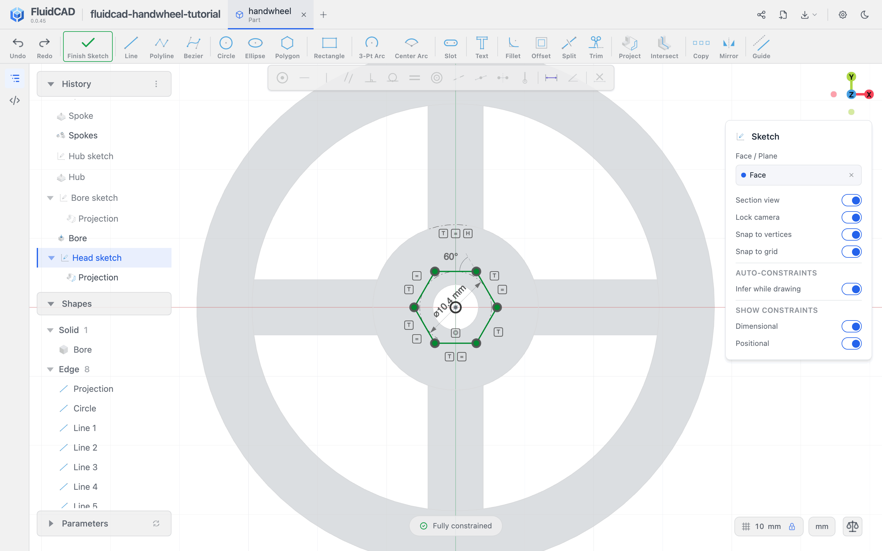
Name the sketch Head sketch. Finish it and open Extrude in Remove mode. Turn Through all off and enter a Distance of 4.5.
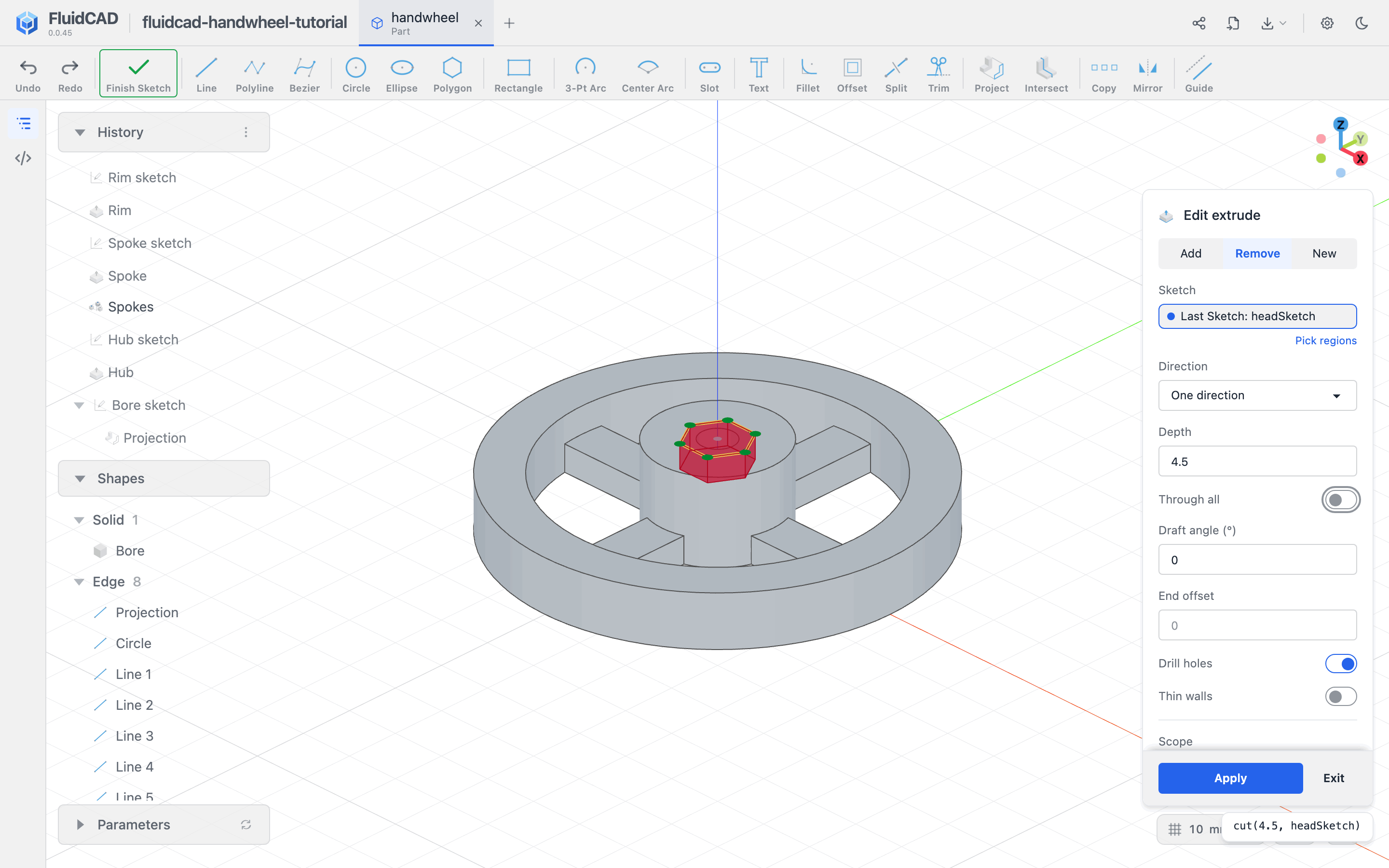
Apply and name it Head pocket. The pocket has a flat seat around the smaller through-hole. A bolt enters from the top, with its shank pointing through the underside.
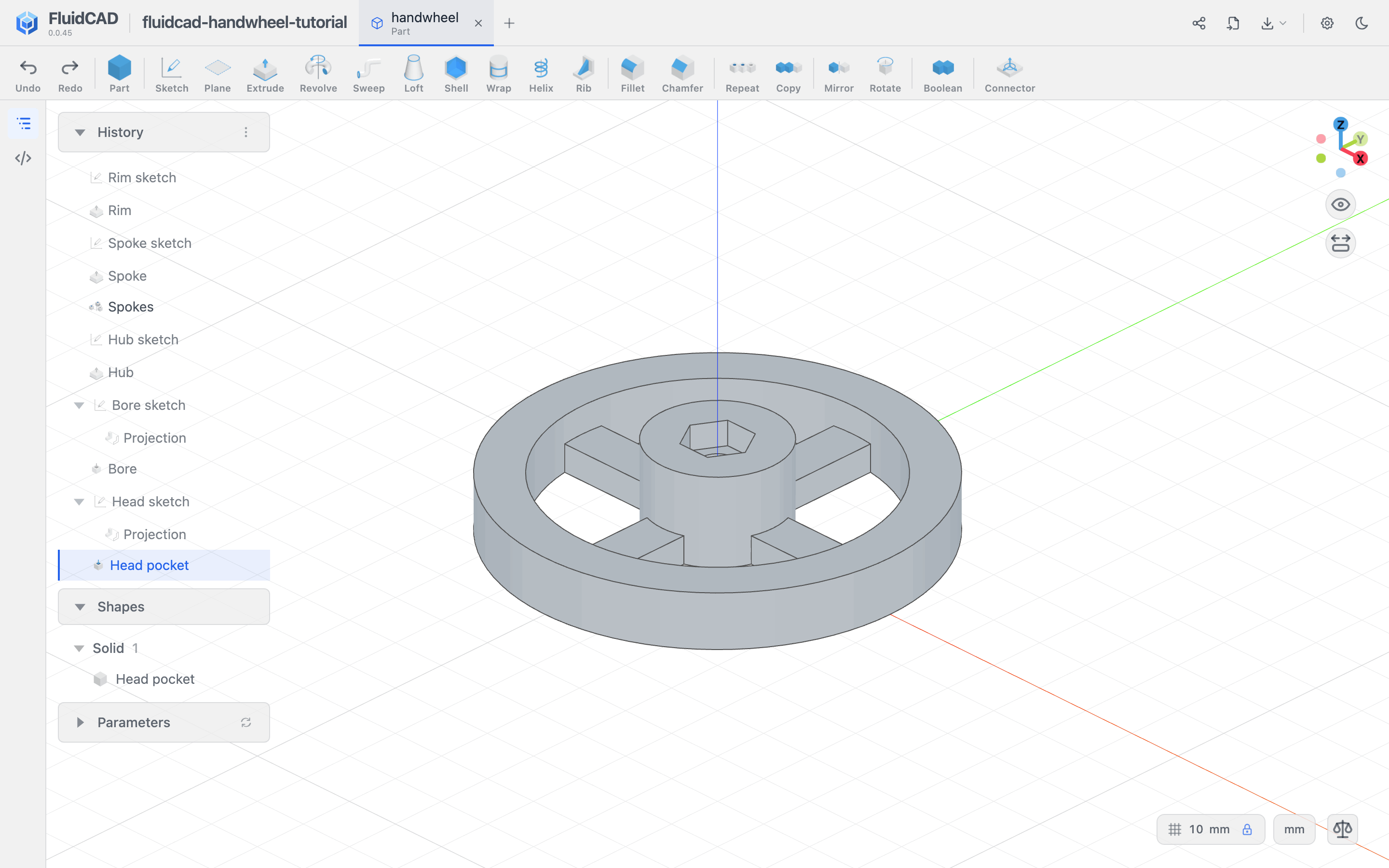
Step 6: Cut, round, and repeat the grip
Locate the first grip circle
Start a sketch on the rim's top face. Project the outer circular edge and make it a Guide. Draw a circle to the right of the wheel with diameter 12.
Constrain the new circle's center horizontally with the projected circle's center using Horizontal, then dimension the distance between those centers to 42. Dimension the center points, not the circumferences.
This places the near side of the circle at 36 mm from the wheel axis. The rim's outside radius is 37.5 mm, so the cut takes a shallow 1.5 mm bite from the edge.
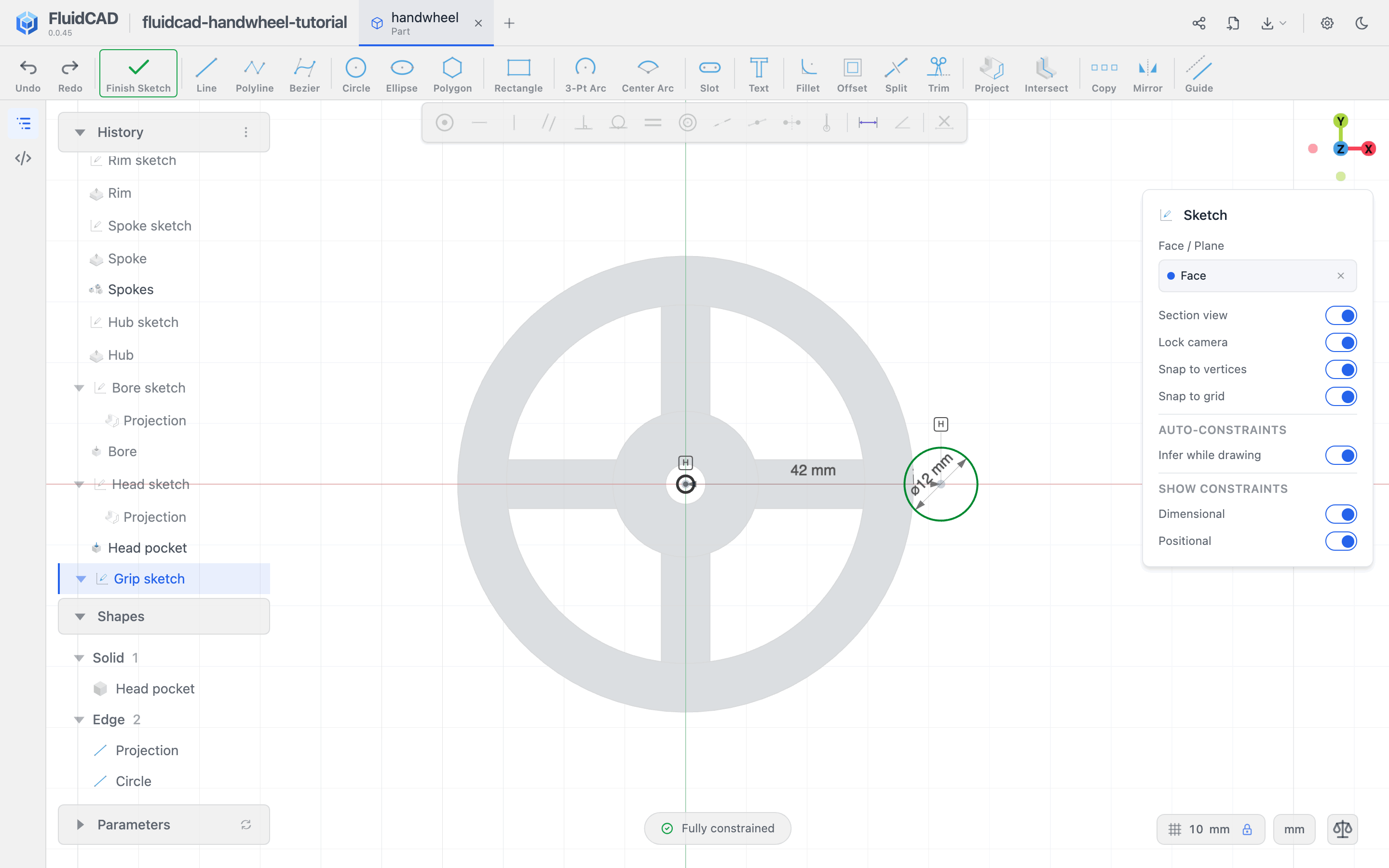
Name it Grip sketch. Finish the sketch, open Extrude, choose Remove, and enable Through all.
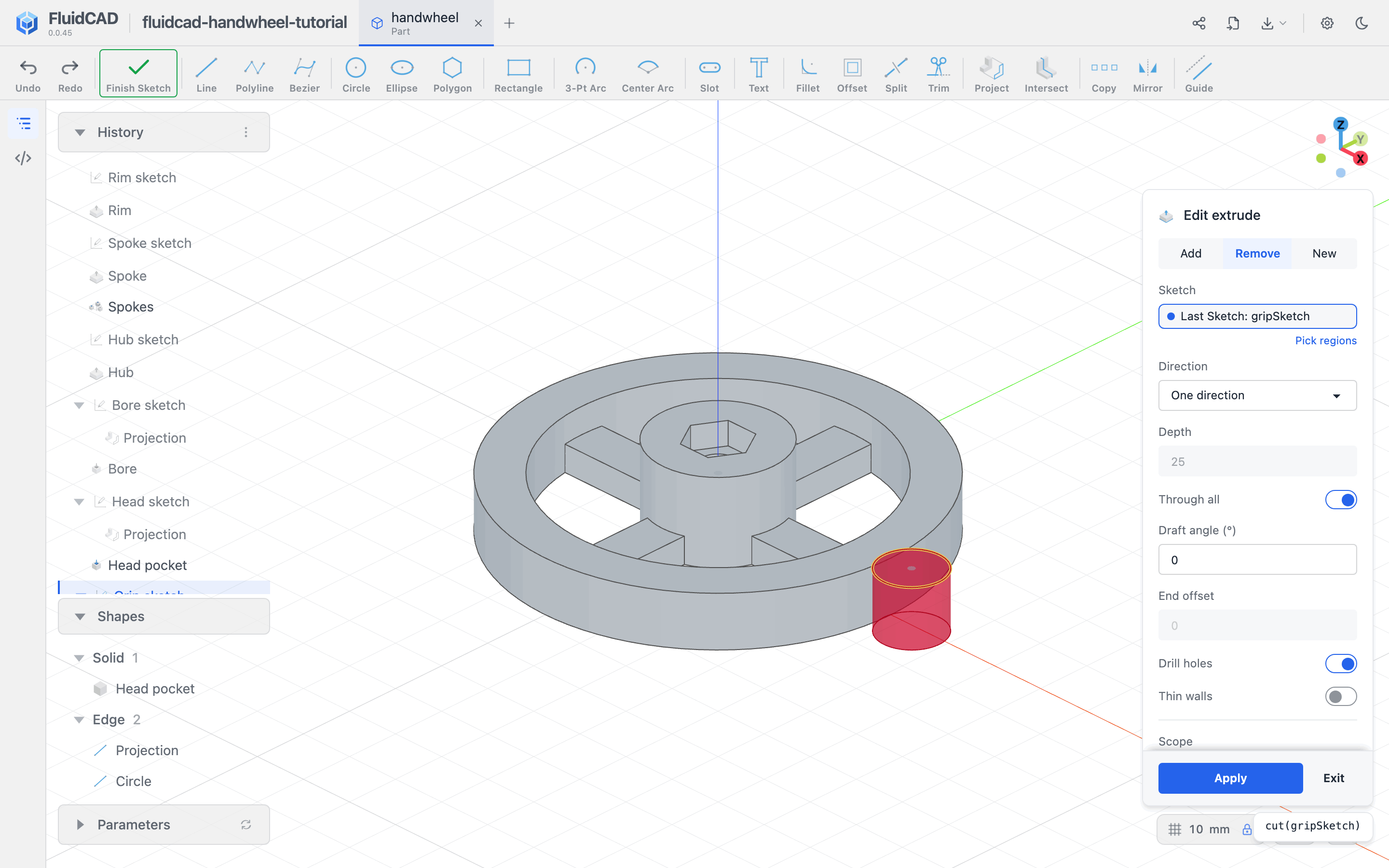
Apply and name it Grip cut.
Round its two vertical edges first
Open Fillet. Pick the two vertical edges where the new cut meets the outside of the rim. Use Ctrl+click for the second edge and set Radius to 2.
These are the two edges running from the bottom to the top of the rim. Leave the upper and lower curved edges out of this selection. The preview should blend the notch into the circumference on both sides.
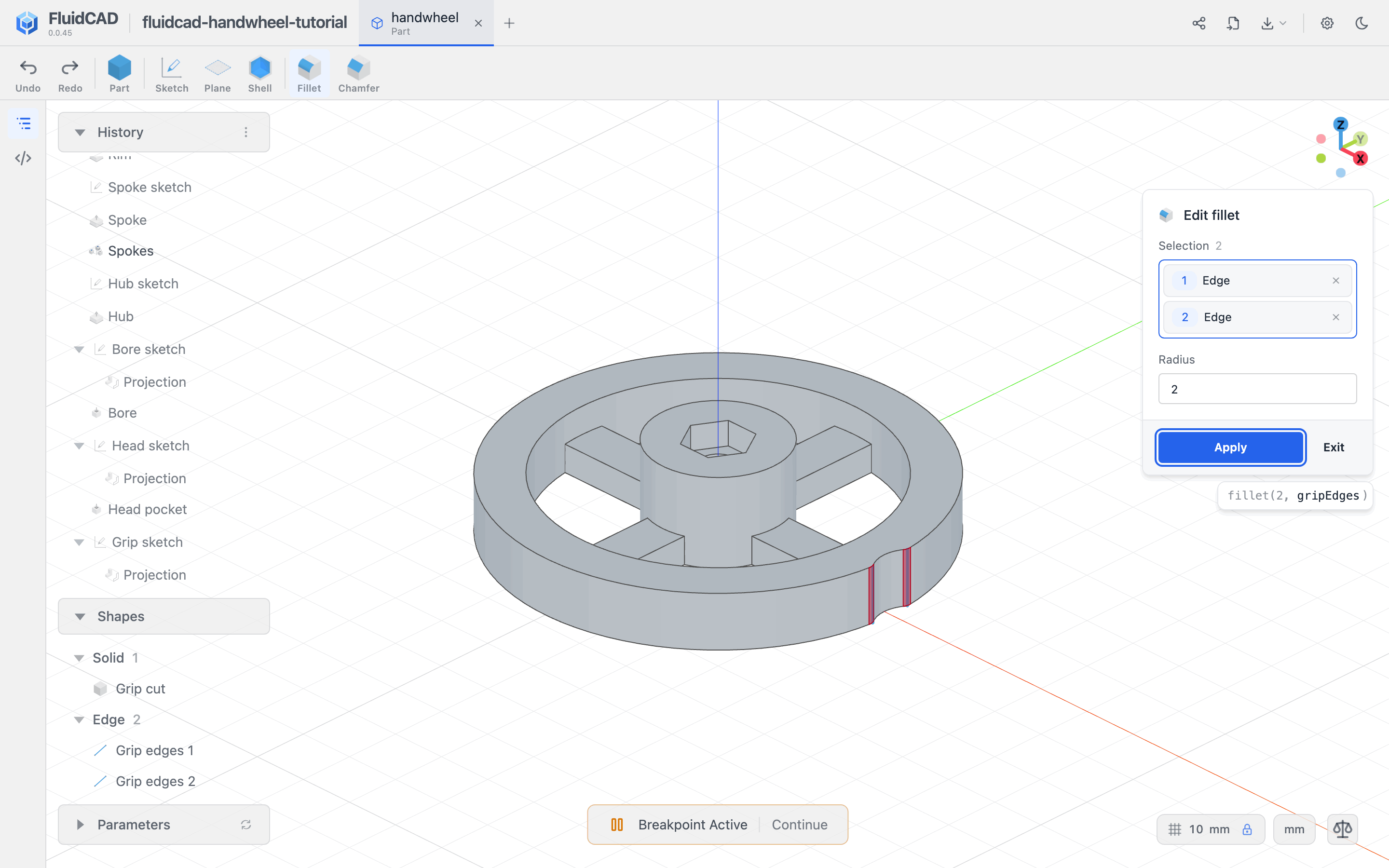
Apply and name the feature Grip fillet.
Repeat both features together
Open Repeat and choose Circular. In History, pick Grip cut and Grip fillet so both appear in the Features slot. Use World Z axis, Total Count 12, and total angle 360.
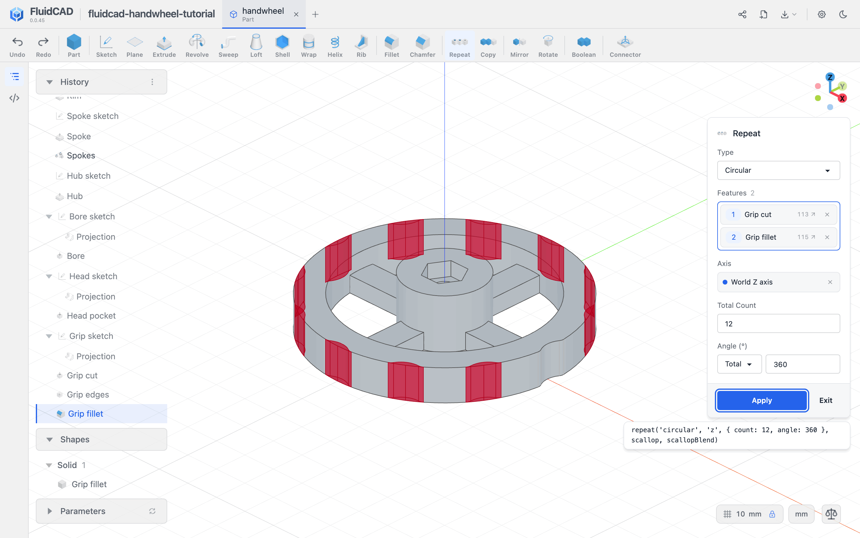
Apply and name the feature Grip pattern. Each instance repeats the cut followed by its two edge fillets. Repeating only the cut would leave eleven sharp notches.
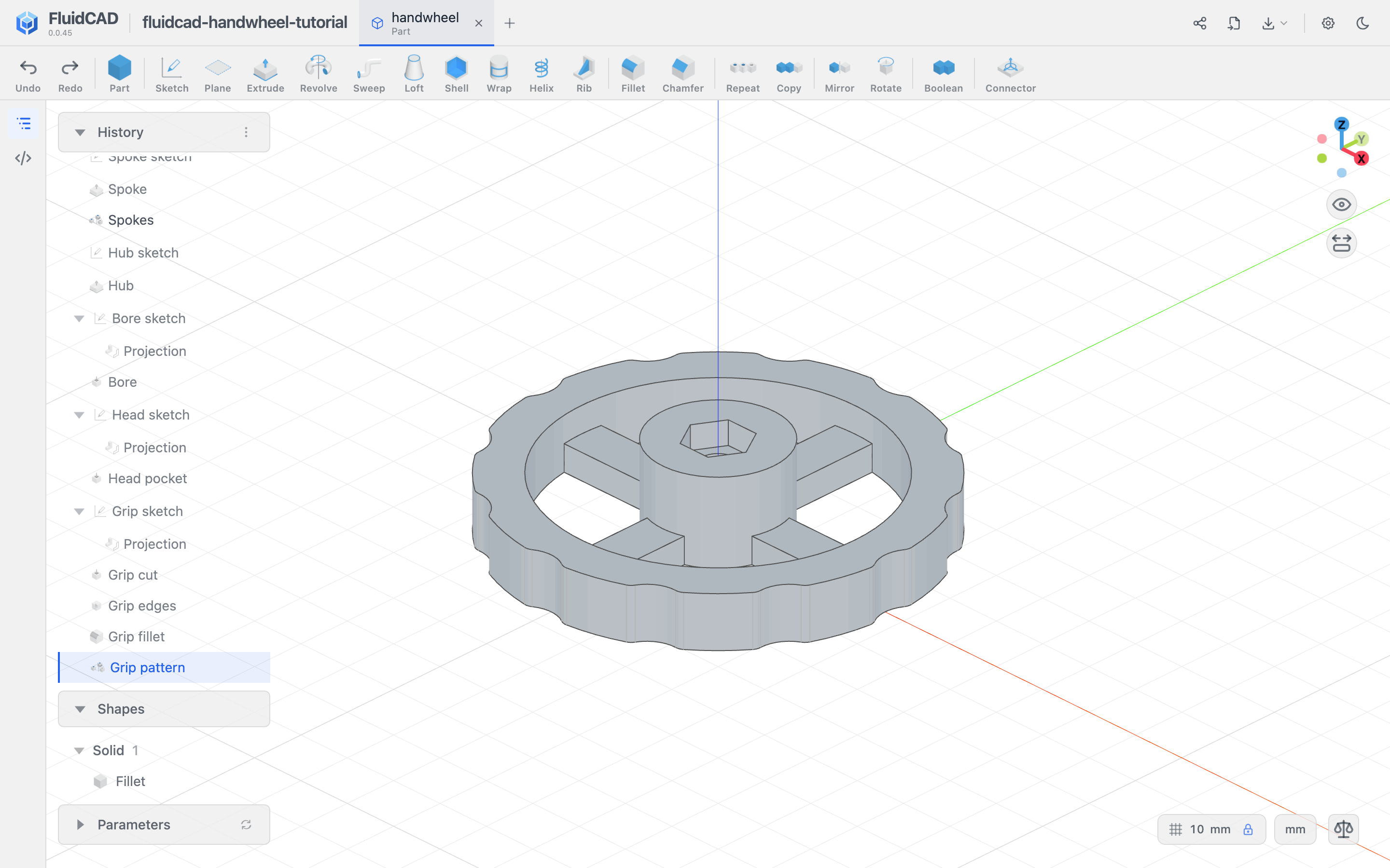
Step 7: Round the remaining edges
Blend the spoke junctions
Open Fillet and set Radius to 2. The edges to round are the short vertical edges where the spokes join the hub and the rim: four per opening, sixteen in total. They all share the spokes' 5 mm height, so you can select them together instead of one by one.
Right-click one of them, for example where a spoke meets the hub, and choose Equal Length Lines (16). Hovering the item highlights the edges it will add; clicking it adds all sixteen, including the ones on the far side. Selection should read 16.
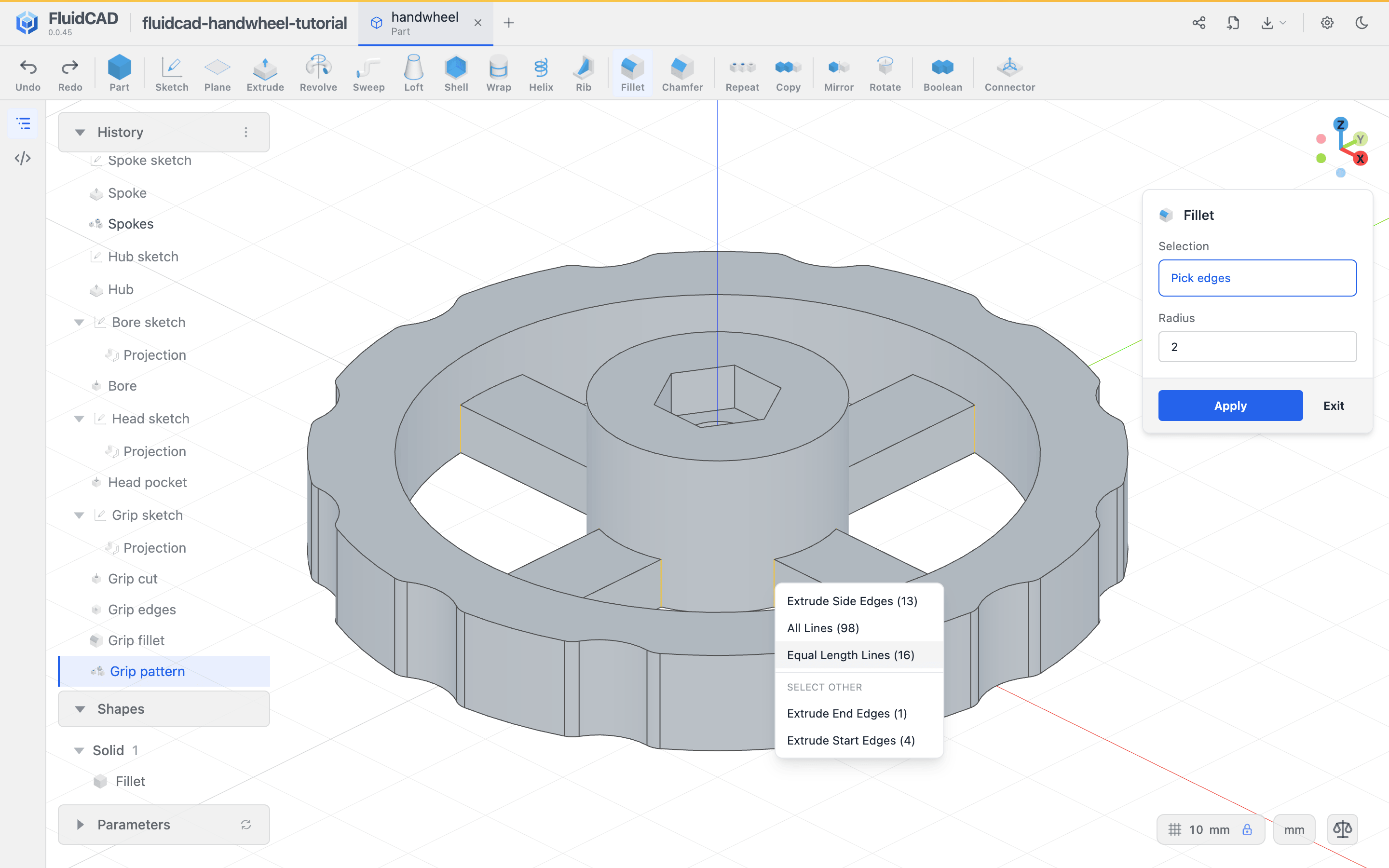
Apply and name this feature Spoke fillets.
Soften the top of the grip
Open Fillet again. Select the rim's outer upper perimeter, including the grip notches and their small blends, then add the inner circular upper edge. Double-click an edge to expand its selection to its group, and check the preview goes all the way around. Set Radius to 1.5.
The earlier vertical fillets make the outer perimeter tangent through each notch, giving this top fillet smooth transitions to follow.
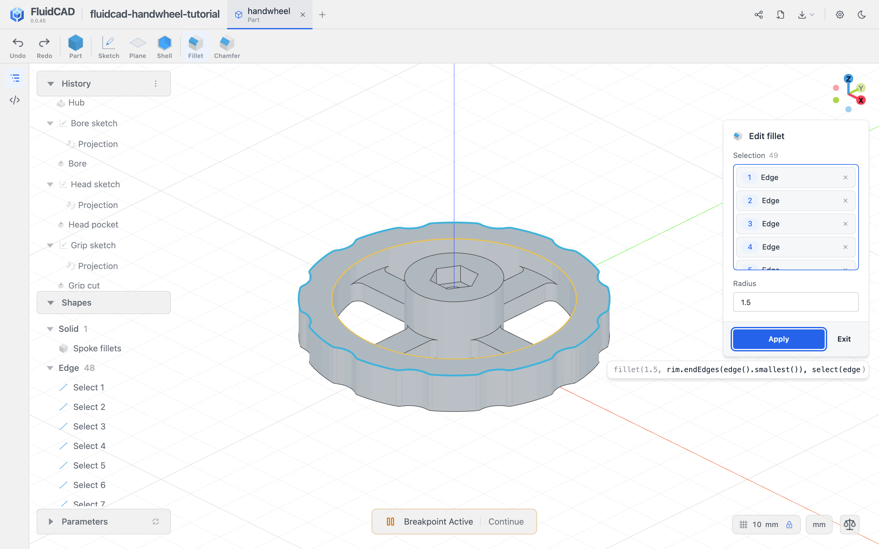
Apply and name it Rim fillet.
Finish the hub and pocket entrance
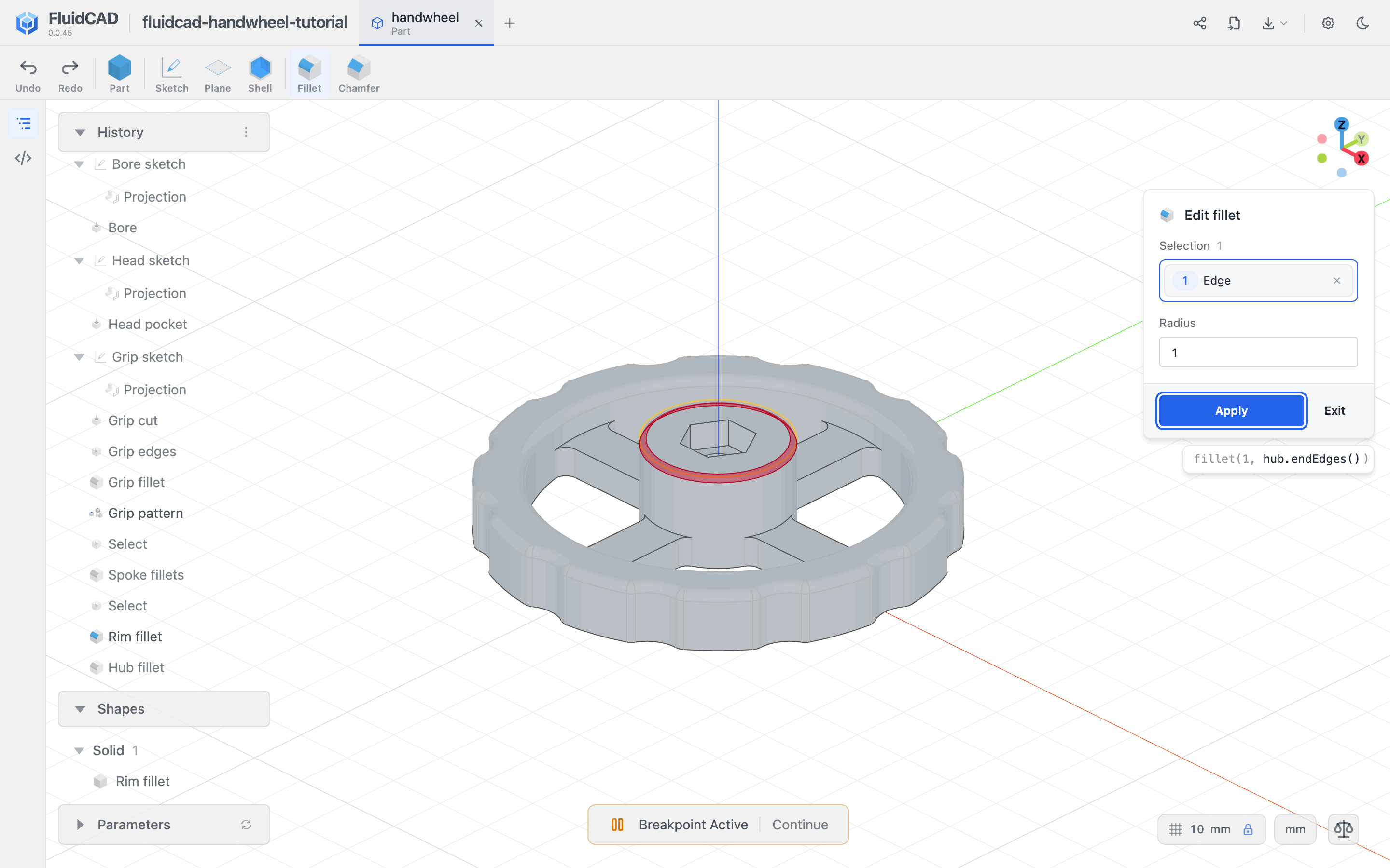
Fillet the hub's outer top circle with radius 1. Keep the hex pocket's edges out of this selection. Name it Hub fillet.
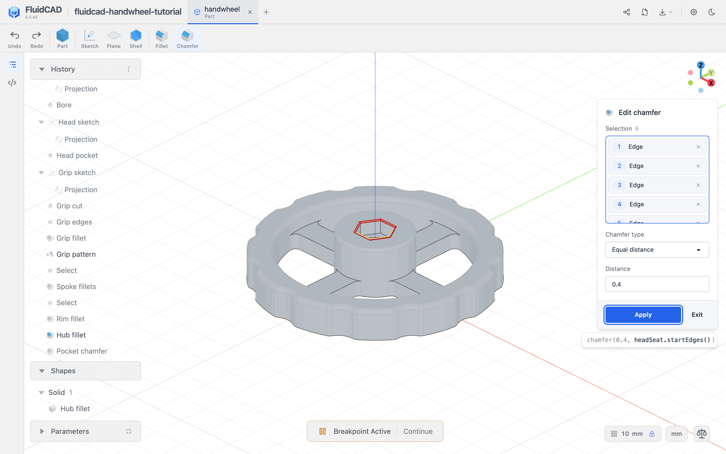
Then open Chamfer, select the six edges at the hex pocket's mouth, and use Equal distance with Distance 0.4. This adds a small lead-in while leaving the pocket walls at 10.4 mm across flats. Apply and name it Pocket chamfer.
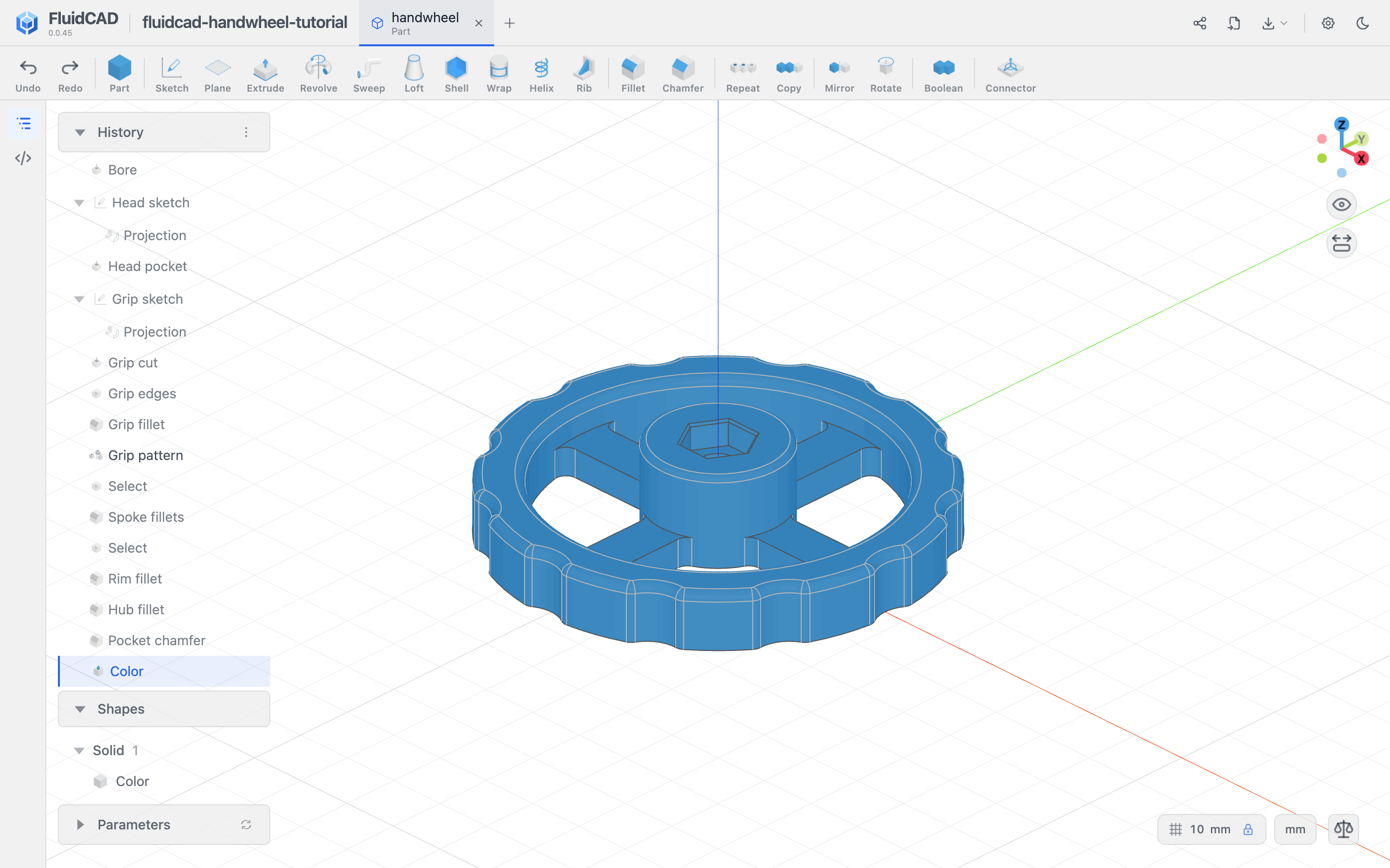
The completed example is colored steel blue; color does not affect the geometry.
For printing, use the top-bar Export control to export the solid as STL. Place the flat underside on the bed, with the hex pocket opening upward. Check the sliced model and hardware fit before using the wheel; this example has been checked as a CAD solid, not physically test-printed.
Full code
The listing below builds the same part, with named dimensions and short feature names. The hexagon uses the constraints emitted by the circumscribed Polygon tool. Your clicked coordinates and generated variable names may differ; the dimensions and constraints determine the final geometry.
Show the full code
import { sketch, circle, line, origin, extrude, project, cut, repeat, select, fillet, chamfer, color } from "fluidcad/core";
import { coincident, diameter, horizontal, vertical, distance, concentric, equal, fix, tangent, angle } from "fluidcad/constraints";

import { edge } from "fluidcad/filters";

// Dimensions are in millimetres, the browser viewer's default unit.

// ASSUMPTION: a compact workshop handwheel, flat underside on XY and shaft on Z.
const wheelDiameter = 75;
const rimWidth = 8;
const rimInnerDiameter = wheelDiameter - 2 * rimWidth;
const hubDiameter = 24;
const spokeWidth = 8;
const spokeHeight = 5;
const spokeCount = 4;
const spokeLength = rimInnerDiameter / 2 + rimWidth / 2;
const rimHeight = 10;
const hubHeight = 16;
// ASSUMPTION: nominal M6 hardware envelope; verify fit with the actual bolt and printer.
const shaftDiameter = 6.6;
const headAcrossFlats = 10.4;
const headPocketDepth = 4.5;
const scallopDiameter = 12;
const scallopDepth = 1.5;
const scallopCenterRadius = wheelDiameter / 2 + scallopDiameter / 2 - scallopDepth;
const scallopCount = 12;
const junctionRadius = 2;
const gripRadius = 1.5;
const scallopBlendRadius = 2;
const hubEdgeRadius = 1;
const pocketChamfer = 0.4;

// 1. A simple annular sketch makes the grip rim.
const rimSketch = sketch("xy", () => {
  const outer = circle([0, 0], wheelDiameter);
  const inner = circle([0, 0], rimInnerDiameter);
  coincident(outer.center(), origin());
  concentric(inner, outer);
  diameter(outer, wheelDiameter);
  diameter(inner, rimInnerDiameter);
}).name("Rim sketch");
const rim = extrude(rimHeight, rimSketch).name("Rim");

// 2. One rectangular spoke reaches from the center into the rim.
const spokeSketch = sketch("xy", () => {
  const b = line([0, -spokeWidth/2], [spokeLength, -spokeWidth/2]);
  const r = line([spokeLength, -spokeWidth/2], [spokeLength, spokeWidth/2]);
  const t = line([spokeLength, spokeWidth/2], [0, spokeWidth/2]);
  const l = line([0, spokeWidth/2], [0, -spokeWidth/2]);
  coincident(b.end(), r.start()); coincident(r.end(), t.start());
  coincident(t.end(), l.start()); coincident(l.end(), b.start());
  horizontal(b); horizontal(t); vertical(r); vertical(l);
  fix(b.start(), [0, -spokeWidth/2]);
  distance(b.start(), b.end(), spokeLength);
  distance(r.start(), r.end(), spokeWidth);
}).name("Spoke sketch");
const spoke = extrude(spokeHeight, spokeSketch).name("Spoke");
const spokePattern = repeat("circular", "z", { count: spokeCount, angle: 360 }, spoke).name("Spokes");

// 3. The central hub has its own single-circle sketch.
const hubSketch = sketch("xy", () => {
  const center = circle([0, 0], hubDiameter);
  coincident(center.center(), origin());
  diameter(center, hubDiameter);
}).name("Hub sketch");
const hub = extrude(hubHeight, hubSketch).name("Hub");

// 4. A separate circle makes the through bore.
const shaftSketch = sketch(hub.endFaces(), () => {
  const hubReference = project(hub.endEdges()).guide();
  const bolt = circle([0, 0], shaftDiameter);
  concentric(bolt, hubReference);
  diameter(bolt, shaftDiameter);
}).name("Bore sketch");
const shaft = cut(shaftSketch).name("Bore");

// 5. A regular hexagon makes the bolt-head seat.
const headSketch = sketch(hub.endFaces(), () => {
  const hubReference = project(hub.endEdges()).guide();
  const headDiameter = headAcrossFlats / Math.cos(Math.PI/6);
  const headRadius = headDiameter/2;
  const hexGuide = circle([0, 0], headAcrossFlats).guide();
  concentric(hexGuide, hubReference);
  diameter(hexGuide, headAcrossFlats);

  const h0 = line([headRadius, 0], [headRadius/2, headAcrossFlats/2]);
  const h1 = line([headRadius/2, headAcrossFlats/2], [-headRadius/2, headAcrossFlats/2]);
  const h2 = line([-headRadius/2, headAcrossFlats/2], [-headRadius, 0]);
  const h3 = line([-headRadius, 0], [-headRadius/2, -headAcrossFlats/2]);
  const h4 = line([-headRadius/2, -headAcrossFlats/2], [headRadius/2, -headAcrossFlats/2]);
  const h5 = line([headRadius/2, -headAcrossFlats/2], [headRadius, 0]);
  coincident(h0.end(), h1.start()); coincident(h1.end(), h2.start());
  coincident(h2.end(), h3.start()); coincident(h3.end(), h4.start());
  coincident(h4.end(), h5.start()); coincident(h5.end(), h0.start());
  tangent(h0, hexGuide); tangent(h1, hexGuide);
  tangent(h2, hexGuide); tangent(h3, hexGuide);
  tangent(h4, hexGuide); tangent(h5, hexGuide);
  equal(h0, h1, h2, h3, h4);
  angle(h0, h1, 60);
  horizontal(h1);

}).name("Head sketch");
const headSeat = cut(headPocketDepth, headSketch).name("Head pocket");

// 6. Cut and soften one grip notch, then repeat both features.
const gripSketch = sketch(rim.endFaces(), () => {
  const rimReference = project(rim.endEdges(edge().largest())).guide();
  const notch = circle([scallopCenterRadius, 0], scallopDiameter);
  horizontal(rimReference.center(), notch.center());
  distance(rimReference.center(), notch.center(), scallopCenterRadius);
  diameter(notch, scallopDiameter);
}).name("Grip sketch");
const scallop = cut(gripSketch).name("Grip cut");
const gripEdges = select(edge().from(scallop.internalEdges())).name("Grip edges");
const scallopBlend = fillet(scallopBlendRadius, gripEdges).name("Grip fillet");
const gripPattern = repeat("circular", "z", { count: scallopCount, angle: 360 }, scallop, scallopBlend).name("Grip pattern");

// 7. Finish the spoke junctions, grip crown, and hardware entrance.
const spokeJunctions = fillet(junctionRadius, select(edge().verticalTo("xy").line(spokeHeight))).name("Spoke fillets");
const gripRound = fillet(gripRadius, select(edge().onPlane("xy", rimHeight))).name("Rim fillet");
const hubRound = fillet(hubEdgeRadius, hub.endEdges()).name("Hub fillet");
const headLeadIn = chamfer(pocketChamfer, headSeat.startEdges()).name("Pocket chamfer");
color("steelblue", headLeadIn);
What you practiced
- Simple, fully constrained circle, rectangle, and polygon sketches.
- Sketching on an origin plane and on a face, with projected guides to locate hardware.
- Additive extrusions, a through bore, and a blind pocket.
- A circular repeat of one spoke and a second repeat containing both a cut and its fillet.
- Choosing the fillet order: vertical grip transitions first, then the upper rim.
- Keeping the hardware seat precise while rounding the surfaces you handle.