Intersect
Intersect cuts the sketch plane through 3D faces and brings the section curves into the sketch. Like a projection, the result is fixed reference geometry: the solver never moves it, it renders as locked (green) geometry, and your sketch geometry can be constrained against it. Where Project flattens what you would see of a face from the sketch plane, Intersect gives you the true outline where the plane passes through it — the wall of a bore, the profile of a curved cavity, the section of a rib.
In the viewport
- Click Intersect on the sketch toolbar. The Intersect dialog opens with one Selection slot.
- Click the 3D faces to section. Each pick becomes a chip; a right-click offers the same multi-select groups the modify tools do. Only faces can be picked — a plane meets an edge in a point, which is no sketch geometry.
- Apply writes the
intersect(…)statement at the top of the sketch body, where the references it creates are available to every constraint after it.
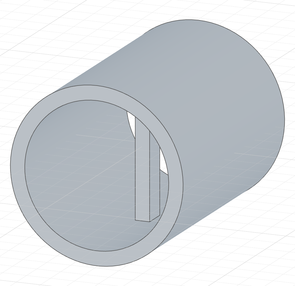
The code behind it
import { sketch, line, circle, extrude, intersect, yAxis } from 'fluidcad/core';
import { coincident, distance, horizontal, vertical, symmetric } from "fluidcad/constraints";

// A Ø60 tube, 100 long with a 6 mm wall — a thin extrude of one circle,
// drawn on the yz plane so the tube runs along X, centred on the plane.
sketch("yz", () => {
    circle([0, 0], 60)
})
const tube = extrude(100).symmetric().thin(6)

// A divider plate, 6 thick, across the middle of the bore. It is drawn on
// the same yz plane, halfway along the tube, where nothing in the sketch
// says how wide the bore is — Intersect does.
sketch("yz", () => {
    // The tube's inner wall cut by the sketch plane: one circle, fixed
    // reference geometry the plate's corners can land on.
    const wall = intersect(tube.internalFaces()).guide()
    const b = line([-3, -24], [3, -24]);
    const r = line([3, -24], [3, 24]);
    const t = line([3, 24], [-3, 24]);
    const l = line([-3, 24], [-3, -24]);
    coincident(b.end(), r.start());
    coincident(r.end(), t.start());
    coincident(t.end(), l.start());
    coincident(l.end(), b.start());
    horizontal(b);
    vertical(r);
    horizontal(t);
    vertical(l);
    distance(b.start(), b.end(), 6);
    symmetric(b.start(), b.end(), yAxis());
    // Two opposite corners on the wall: the plate spans the bore exactly,
    // and follows it if the tube changes.
    coincident(b.start(), wall);
    coincident(t.start(), wall);
})

// The plate, 10 long, centred on the plane like the tube.
extrude(10).symmetric()
Double-click the intersection's row in the timeline to re-source it: the viewport rolls back to just before the statement and the dialog reopens with its faces highlighted.
From another part
Inside a part you can section the faces of a part declared before it, exactly as with Project: the dialog names the owning part, and Apply waits for Expose and intersect, which writes an expose() into that part for each picked face and references it as <part>.features.<name> in your sketch.
By hand
intersect(tube.internalFaces())    // a bore's wall → its circle at the plane
intersect(body)                    // a whole solid → its full section outline
intersect(face1, face2)            // several sources at once
Sections usually carry .guide() so the reference stays out of the profile and only the geometry drawn against it is extruded or cut.
Constraining against a section
A section is a first-class constraint target, with the same forms as a projection: a single sectioned entity is used directly, and a multi-edge section is addressed with .ref(i):
sketch("yz", () => {
    const wall = intersect(tube.internalFaces()).guide()   // one circle
    coincident(b.start(), wall)                              // a corner on the wall
    concentric(c, wall)                                      // a hole concentric with it
})
const outline = intersect(body).guide()          // several edges
coincident(p, outline.ref(0).start())
tangent(outline.ref(2), l)
Because references are fixed, a sketch made only of sections reports Fully constrained by itself — the geometry you add is what brings degrees of freedom.