connector()
A connector is a named coordinate frame attached to the part's geometry — an origin, an X direction and a Z normal. Mates in an assembly join connectors to connectors, so the connectors a part declares are its mating interface. Every instance of the part carries the same set. A bolt circle or a hole grid needs only one: declare it on the first hole and copy it.
In the viewport
- Click Connector on the toolbar. The Connector dialog docks on the right with its Source slot armed.
- Hover the model. Faces and edges float their anchor candidates — the centre of a face, the centre, start or end of an edge — as a translucent frame, and the frame follows the cursor to the anchor nearest it. On an arc, hover its middle for the arc's centre, or near an end for that end. Click the one you want; the chip shows it.
- Fill in the Name (a free
c1-style default is prefilled). Adjust the frame-local Offset x / y / z and click the rotation stepper to turn the frame 90° about its own Z per click. - Click Apply. The statement is written directly in the part body and the timeline's part row gains a connector under its N connectors toggle. In the viewport the connector renders as a small axis triad.

The code behind it
import { part, sketch, line, circle, extrude, cut, plane, select, connector } from 'fluidcad/core';
import { face } from 'fluidcad/filters';
import { coincident, distance, fix, horizontal, vertical } from 'fluidcad/constraints';

// A 40 × 40 × 40 angle bracket, 4 mm thick, with two mounting holes in
// each leg — and named connectors on the faces other parts mate to. In a
// part file the connectors render as small axis triads on their geometry;
// an assembly mates to them as `bracket.connectors.<name>`.
export const bracket = part('Angle bracket', () => {
    // The L profile on the front plane: base along X, upright along Z.
    sketch('xz', () => {
        const l1 = line([0, 0], [40, 0]);
        const l2 = line([40, 0], [40, 4]);
        const l3 = line([40, 4], [4, 4]);
        const l4 = line([4, 4], [4, 40]);
        const l5 = line([4, 40], [0, 40]);
        const l6 = line([0, 40], [0, 0]);
        coincident(l1.end(), l2.start());
        coincident(l2.end(), l3.start());
        coincident(l3.end(), l4.start());
        coincident(l4.end(), l5.start());
        coincident(l5.end(), l6.start());
        coincident(l6.end(), l1.start());
        horizontal(l1);
        horizontal(l3);
        horizontal(l5);
        vertical(l2);
        vertical(l4);
        vertical(l6);
        fix(l1.start(), [0, 0]);
        distance(l1.start(), l1.end(), 40);
        distance(l6.start(), l6.end(), 40);
        distance(l2.start(), l2.end(), 4);
        distance(l5.start(), l5.end(), 4);
    });
    extrude(40).symmetric();

    // Mounting holes: two down through the base, two through the upright.
    sketch(plane('xy', { offset: 4 }), () => {
        circle([25, -12], 5);
        circle([25, 12], 5);
    });
    cut(4);
    sketch(plane('yz', { offset: 4 }), () => {
        circle([-12, 25], 5);
        circle([12, 25], 5);
    });
    cut(4);

    // A face connector sits at the face's centre with Z along its outward
    // normal — the frame another part's face is mated face-to-face against.
    // The underside of the base:
    connector('foot', select(face().planar().onPlane('xy', 0)));
    // The back of the upright, for hanging the bracket on a wall or beam:
    connector('back', select(face().planar().onPlane('yz', 0)));
    // The two base holes: the top-of-base frame moved along its own X / Y
    // to each hole centre, where a standoff or a bolt head seats.
    connector('hole1', select(face().planar().onPlane('xy', 4))).offset(3, -12, 0);
    connector('hole2', select(face().planar().onPlane('xy', 4))).offset(3, 12, 0);
});
The bracket names the faces a neighbour will touch — foot for the surface it stands on, back for the beam it hangs from — and the two holes a fastener seats in. In an assembly, mate('fastened', beam.connectors.side, bracket.connectors.back) hangs it on the beam.
Signature
connector(name, source, options?)
| Argument | Meaning |
|---|---|
name | Identifier, unique within the part. Reached as instance.connectors.<name>. |
source | The geometry the frame is derived from — see below. |
options.xDirection | Optional X direction (an axis name or vector), re-orthogonalised against the frame's Z. |
Two chained modifiers move the frame after it is derived, in call order:
| Modifier | Effect |
|---|---|
.offset(x, y?, z?) | Translate the origin along the frame's own axes. |
.rotate('x' | 'y' | 'z', degrees) | Rotate the frame about one of its own axes, pivoting at its origin. |
Where the frame comes from
| Source | Origin | Z |
|---|---|---|
A planar face — select(face().onPlane('xy', 10)) | Face centre | Face normal, pointing out of the solid |
A cylindrical or conical face — select(face().cylinder()) | On the axis, at the face's mid-height | The surface axis, always oriented up (or +Y / +X when horizontal), never toward the seam |
A circular edge — select(edge().circle()) | Circle centre | Circle axis |
A straight edge — select(edge().line()) | Edge midpoint | Edge tangent |
| A vertex | The point | World Z |
An anchored vertex — e.endFaces().center(), sel.start(), sel.end() | The anchor point | The anchored face or edge's own direction |
A plane — plane('xy', { offset: 20 }) | Plane origin | Plane normal |
The source must resolve to exactly one face, edge or vertex. A raw point is refused on purpose: a frame tied to geometry re-derives correctly when the part changes; a hard-coded point would drift.
Face frames follow the outward normal, so two parts mated face-to-face end up with their connector Zs pointing at each other — that is the default a mate assumes, and .flip() on the mate is how you get the other way round.
Rules
- Declare connectors directly in the part body, not inside a
sketch()or other callback — nested, the connector would register nowhere and the statement is refused. - Names are unique within a part; a part connector and an assembly connector may share a name.
- Connectors are part-owned. There is no way to add one to a single instance from the assembly; edit the part, or use an assembly-level free frame (
connector('name', [x, y, z]), see the assembly introduction). - The pen button on a connector chip in the mate dialog edits a part connector's name, offset and rotation from the assembly — the edit is written into the part file.
Copying a connector
A copy of a connector is a connector too — a mate side, a replicate row — with no statement of its own. The copies of bolt are addressed bolt.instance(1), bolt.instance(2), …; in these pages bolt.instance(3) is copy 3 of bolt.
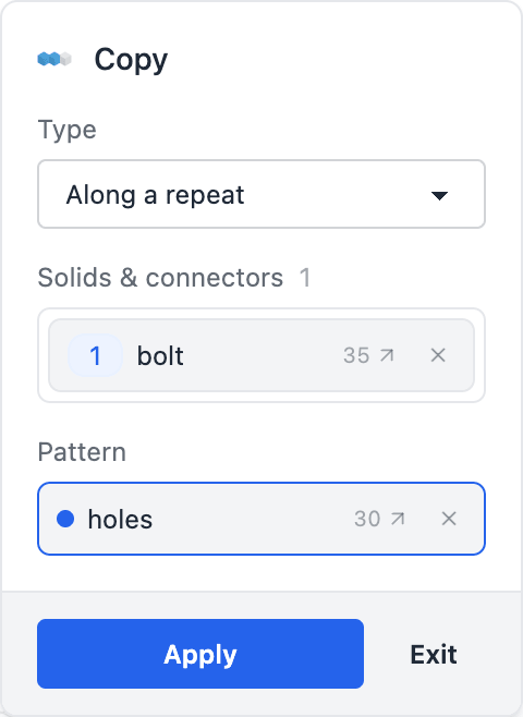
- Right-click the connector's row in the timeline (under the part's N connectors toggle) and choose Copy…. The Copy dialog opens with the connector in its Solids & connectors slot. Or click Copy on the toolbar and click the connector's triad: every connector shows while the dialog is open.
- Pick the Type. Along a repeat puts one copy on every instance of a feature you repeated: its Pattern slot asks for the repeat — click the Repeat row in the timeline, or the repeated feature in the viewport. Count, spacing and axis come from the repeat, so the dialog hides them. Linear and Circular lay the copies out on their own, with the fields of a solid copy; their Axis slot also takes a connector, for its Z axis.
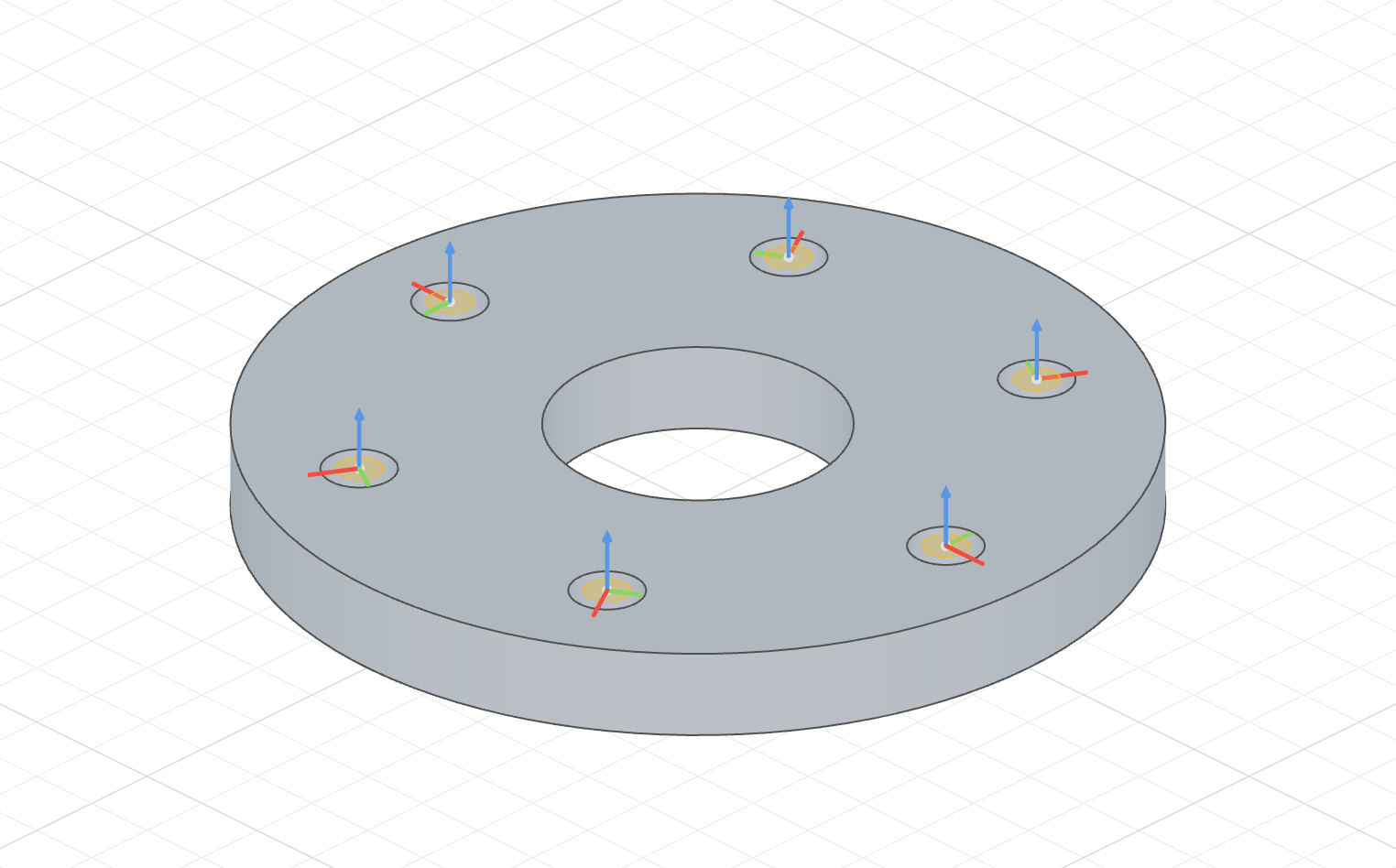
- A translucent triad previews each copy. Click Apply. The
copy()statement is written at the end of the part body, and its Copy row appears in the timeline like any other feature; clicking the row highlights the connector with all its copies.
The code behind it
import { part, sketch, circle, extrude, cut, repeat, connector, copy, origin } from 'fluidcad/core';
import { coincident, diameter, fix } from 'fluidcad/constraints';

// A Ø120 pipe flange, 12 mm thick, with a Ø40 bore and six Ø10 bolt holes
// on a Ø90 bolt circle. Each hole gets a connector a bolt mates to — one
// declared on the first hole, and a copy of it on each of the other five.
export const flange = part('Pipe flange', () => {
    sketch('xy', () => {
        const rim = circle([0, 0], 120);
        coincident(rim.center(), origin());
        diameter(rim, 120);
    });
    const disc = extrude(12);

    sketch(disc.endFaces(), () => {
        const bore = circle([0, 0], 40);
        coincident(bore.center(), origin());
        diameter(bore, 40);
    });
    cut();

    // One bolt hole on the bolt circle, cut through, then repeated six
    // times around Z by the Repeat dialog.
    sketch(disc.endFaces(), () => {
        const c = circle([45, 0], 10);
        diameter(c, 10);
        fix(c.center(), [45, 0]);
    });
    const hole = cut();
    const holes = repeat('circular', 'z', { count: 6, angle: 360 }, hole);

    // The bolt seat on the first hole: its round top edge gives the frame
    // — origin at the hole's centre, Z along the hole's axis.
    const bolt = connector('bolt', hole.startEdges());
    // Copy dialog, type "Along a repeat": one copy of `bolt` on each hole
    // the repeat cut. bolt.instance(k) sits on holes.instance(k), so copy 3
    // of `bolt` is the hole three steps round. Change the repeat's count
    // and the copies follow it.
    copy(holes, bolt);
});
An assembly mates a copy like any connector: mate('fastened', f.connectors.bolt.instance(3), b.connectors.head) seats a bolt in the hole three steps round from the first. Dialog chips show the same spelling, Pipe flange · bolt.instance(3).
How copies behave
- Read-only. A copy is not edited, renamed or removed on its own. Change the connector and every copy follows; change the pattern by double-clicking the Copy row. In the mate dialog, the pen on a copy's chip edits the connector it copies, and says so.
- Numbered like a repeat's instances. Along a repeat,
bolt.instance(k)sits on the repeat's instancek, and an instance the repeat skips has no copy. A linear grid counts its cells with the first direction varying slowest, the original keeping its own cell (0, or the centre cell when centered); a circular copy counts the steps round from the original at 0. The original's own slot is the connector itself. - A moved frame, not a new anchor. A copy is the connector's frame moved by the pattern. It does not re-attach to the geometry where it lands, so a Linear or Circular copy sits on a hole only while its pattern matches the holes'. Along a repeat keeps every copy on its hole when the repeat's count, spacing or axis changes, and it is the way to follow a repeat over a partial arc: a Circular copy steps that arc differently (see Copy).
- Renumbering. A grid's cells are numbered in one sequence, so changing a later direction's count, or the count of a centered pattern, gives the slots new numbers: a part mated to
hole.instance(2)of a 2 × 2 grid jumps to another hole when the grid becomes 2 × 3. The jump shows in the assembly, so it does not go unnoticed. - Limits. One copy statement per connector; a copy is not copied again (a grid is one Linear copy with two directions); copies are made directly in the part body, never in a sketch. A Circular copy of a connector can't be Centered yet.
- Addresses that don't exist. A slot the pattern skipped, a slot past the count, or
.instance()on a connector nothing copies stops the assembly with an error that names the copy statement:bolt.instance(7) is out of range — the copy at flange.part.js:40 makes instances 0–5.