Gear relation
A relation couples two joints: turn one and the other turns with it, by a ratio. A gear relation ties the rotations of two revolute (or cylindrical) mates — meshing gears, a belt drive, a pulley pair. A rack and pinion relation ties a rotation to the travel of a slider (or cylindrical) mate. The joints keep their own freedom: drag either part, or animate either joint, and both move.
| Relation | Mate A | Mate B | Ratio |
|---|---|---|---|
| Gear | revolute or cylindrical | revolute or cylindrical | turns of B per turn of A |
| Rack and pinion | revolute or cylindrical (the pinion) | slider or cylindrical (the rack) | travel of B per turn of A |
In the viewport
- Mate each gear to its axle with a Revolute mate first — a relation couples existing joints.
- Click Gear on the assembly toolbar (or Rack for a rack and pinion). The Joints panel switches to picking: click the first joint's row, then the second's. Clicking a part in the viewport offers the joints on that part instead.
- Set the Ratio — how many turns the second joint makes per turn of the first. Two external gears on parallel axes turn opposite ways, so tick Reverse for a meshing pair.
- Drag a gear while the dialog is open: the other one turns with it. Click Apply. The relation gets its own row in the Joints panel, under the joints it couples.
The code behind it
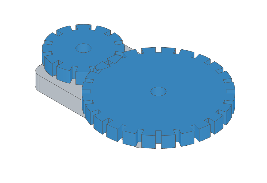
Both mates are bound to a const so the relation can name them. The axles are assembly connectors placed on the plate's top face; the gears' bore frames face down to meet them. The ratio is the pinion's tooth count over the wheel's:gear.part.js
import { assembly, insert, mate, relation, connector } from 'fluidcad/core';
import { plate } from './asm-plate.part.js';
import { gear } from './asm-gear.part.js';

export const gearTrain = assembly('gear-train', () => {
    const base = insert(plate).grounded();
    // A 12-tooth pinion driving a 24-tooth wheel, 54 mm apart (the sum of
    // their pitch radii, 18 + 36).
    const pinion = insert(gear, { teeth: 12 }).translate(-27, 0, 10);
    const wheel = insert(gear, { teeth: 24 }).translate(27, 0, 10);

    // Two axle frames on the plate's top face, as assembly connectors.
    const axle1 = connector('axle1', [-27, 0, 10]);
    const axle2 = connector('axle2', [27, 0, 10]);
    const pinionAxle = mate('revolute', axle1, pinion.connectors.bore);
    const wheelAxle = mate('revolute', axle2, wheel.connectors.bore);

    // The gear relation: the wheel makes half a turn per pinion turn, and
    // turns the other way — external gears on parallel axes counter-rotate.
    relation('gear', pinionAxle, wheelAxle, 0.5).reverse();
});
Options
relation('gear', pinionAxle, wheelAxle, 0.5)
    .reverse()            // the wheel turns against the pinion's sense
    .name('drive')        // a stable name, unique within the assembly

// A rack: 20 mm pitch radius → 2π·20 ≈ 125.66 mm of travel per pinion turn.
relation('rack-and-pinion', pinionAxle, rackSlide, 125.66);
How the coupling works
Each rotation is measured about its own mate's Z axis, each travel along it, so the sign depends on how the connectors point: a positive ratio moves the second joint in the same sense as the first, Reverse the opposite. The relation holds from wherever the parts stand when it is first solved — the file's poses set the mesh phase. Rotate a gear's insert() to re-phase the teeth.
A planar mate frees two directions and a spin, so it has no single travel to couple: put a rack on a slider mate. When a solve cannot hold the ratio — one of the coupled joints is held by another mate, say — the relation's row shows a red dot.