Split
Split divides a solid along a plane, or along the surface a sketch edge sweeps out of its sketch. Keep both sides as separate solids, or keep just one side to trim the model. Use it to divide a housing or separate a model into pieces for printing. Each new cut face closes the resulting solid.
In the viewport
- Finish any open sketch, then click Split on the toolbar.
- Choose the cut in the Cut slot. You can pick an origin plane, a plane feature in the viewport or timeline, a planar face, or a sketch edge: a straight line cuts along the plane it defines, and an arc, circle, ellipse or spline cuts along the curved surface it sweeps. The Cut slot is active when the dialog opens.
- To limit the operation, click the Solids slot, then click a face or edge of a target solid, or its feature row in the timeline. Leave Solids empty to use all solids in the current scope. Inside a part, that means the solids in that part.
- In the Keep dropdown, choose Both sides, Front side, or Back side to set which pieces to keep. The cut is at the selected plane itself; to cut somewhere else, create an offset plane with the Plane tool first and pick that.
- Check the preview, then click Apply. FluidCAD adds a Split feature to the timeline and writes the statement to your file.
The preview shows a translucent cutting surface. With Front side or Back side selected, pieces that will be removed appear red. Click the Cut or Solids slot before picking in the viewport to choose what the next click selects.
Targets are selected by feature. If a feature produced several solids, selecting it can include all of those solids.
To change an existing split, double-click its timeline row. You can replace the cut, change the targets, or adjust the keep side.
Split at an offset plane
For this 80 × 60 × 20 block, first create a plane 10 units from YZ with the Plane tool, then pick that plane in the Cut slot and keep Both. The cut is at x = 10, leaving pieces that are 50 and 30 units wide. The plane feature is hidden once the split consumes it; its timeline eye shows it again.

The code behind it
import { sketch, line, extrude, plane, split } from "fluidcad/core";
import { coincident, distance, fix, horizontal, vertical } from "fluidcad/constraints";

const width = 80;
const depth = 60;
const height = 20;
const cutOffset = 10;

// Draw a centred rectangle. Constraints join its corners, square its
// sides, and fix its position and size.
sketch("xy", () => {
  const b = line([-width / 2, -depth / 2], [width / 2, -depth / 2]);
  const r = line([width / 2, -depth / 2], [width / 2, depth / 2]);
  const t = line([width / 2, depth / 2], [-width / 2, depth / 2]);
  const l = line([-width / 2, depth / 2], [-width / 2, -depth / 2]);
  coincident(b.end(), r.start());
  coincident(r.end(), t.start());
  coincident(t.end(), l.start());
  coincident(l.end(), b.start());
  horizontal(b);
  vertical(r);
  horizontal(t);
  vertical(l);
  fix(b.start(), [-width / 2, -depth / 2]);
  distance(b.start(), b.end(), width);
  distance(r.start(), r.end(), depth);
});
const block = extrude(height);

// The cut plane: the YZ plane moved 10 along its normal, which points along +X.
const cutPlane = plane("yz", cutOffset);

// Cut at x = 10. The default is to keep both pieces. They remain in their original
// positions, touching at the cut; Split does not move them apart.
const pieces = split(cutPlane, block);
The pieces stay in their original positions and touch at the cut. Split does not create a gap or move them apart. Both pieces belong to the Split feature; a later operation targeting that feature acts on all its retained pieces.
Keep both sides or trim one side
Front means the side the cutting plane's normal points toward. Back means the opposite side. These directions belong to the plane and do not change when you rotate the view.
For the same block and cut at x = 10:
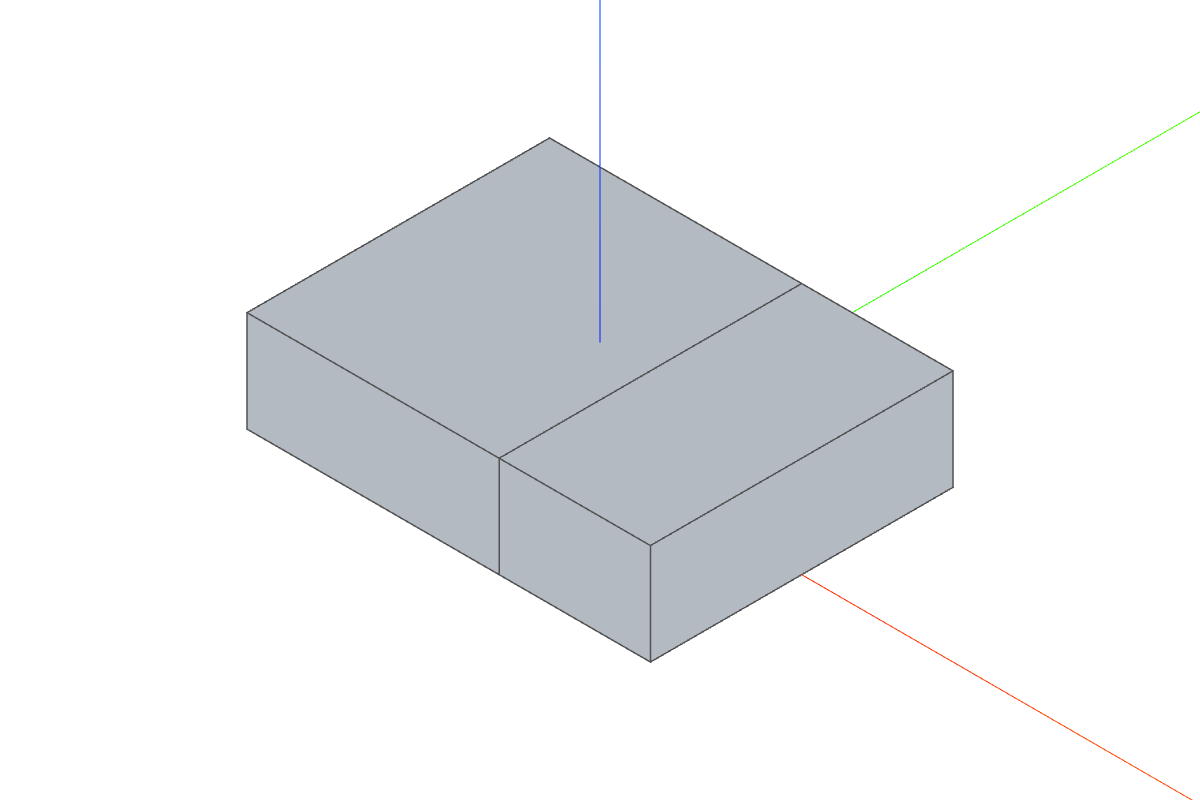
Keeps the 50-unit and 30-unit pieces as two solids.
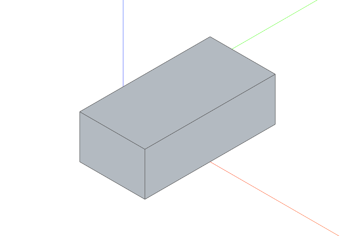
Keeps the 30-unit piece on the +X side of the cut.
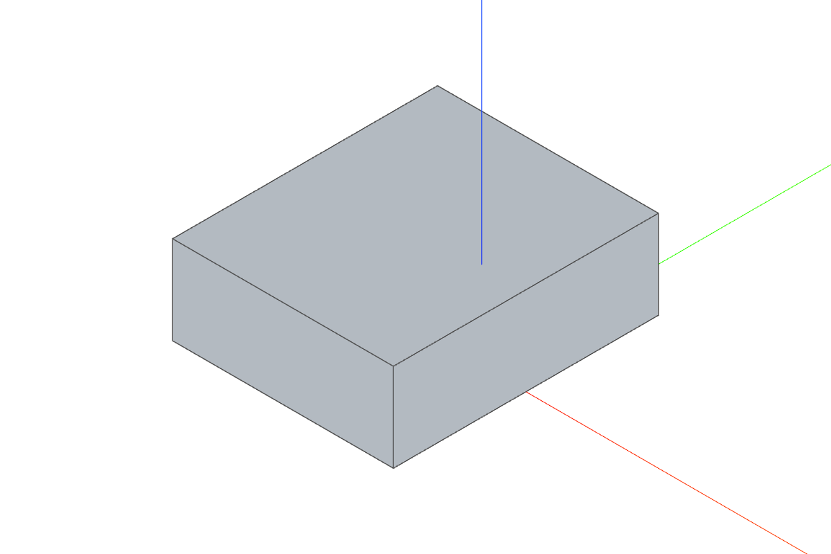
Keeps the 50-unit piece on the −X side of the cut.
Keep the front side
import { sketch, line, extrude, plane, split } from "fluidcad/core";
import { coincident, distance, fix, horizontal, vertical } from "fluidcad/constraints";

const width = 80;
const depth = 60;
const height = 20;
const cutOffset = 10;

// Draw a centred rectangle. Constraints join its corners, square its
// sides, and fix its position and size.
sketch("xy", () => {
  const b = line([-width / 2, -depth / 2], [width / 2, -depth / 2]);
  const r = line([width / 2, -depth / 2], [width / 2, depth / 2]);
  const t = line([width / 2, depth / 2], [-width / 2, depth / 2]);
  const l = line([-width / 2, depth / 2], [-width / 2, -depth / 2]);
  coincident(b.end(), r.start());
  coincident(r.end(), t.start());
  coincident(t.end(), l.start());
  coincident(l.end(), b.start());
  horizontal(b);
  vertical(r);
  horizontal(t);
  vertical(l);
  fix(b.start(), [-width / 2, -depth / 2]);
  distance(b.start(), b.end(), width);
  distance(r.start(), r.end(), depth);
});
const block = extrude(height);

// The cut plane: the YZ plane moved 10 along its normal, which points along +X.
const cutPlane = plane("yz", cutOffset);

// Keep the 30-wide piece on the +X side of the cut.
split(cutPlane, { keep: "front" }, block);
Keep the back side
import { sketch, line, extrude, plane, split } from "fluidcad/core";
import { coincident, distance, fix, horizontal, vertical } from "fluidcad/constraints";

const width = 80;
const depth = 60;
const height = 20;
const cutOffset = 10;

// Draw a centred rectangle. Constraints join its corners, square its
// sides, and fix its position and size.
sketch("xy", () => {
  const b = line([-width / 2, -depth / 2], [width / 2, -depth / 2]);
  const r = line([width / 2, -depth / 2], [width / 2, depth / 2]);
  const t = line([width / 2, depth / 2], [-width / 2, depth / 2]);
  const l = line([-width / 2, depth / 2], [-width / 2, -depth / 2]);
  coincident(b.end(), r.start());
  coincident(r.end(), t.start());
  coincident(t.end(), l.start());
  coincident(l.end(), b.start());
  horizontal(b);
  vertical(r);
  horizontal(t);
  vertical(l);
  fix(b.start(), [-width / 2, -depth / 2]);
  distance(b.start(), b.end(), width);
  distance(r.start(), r.end(), depth);
});
const block = extrude(height);

// The cut plane: the YZ plane moved 10 along its normal, which points along +X.
const cutPlane = plane("yz", cutOffset);

// Keep the 50-wide piece on the -X side of the cut.
split(cutPlane, { keep: "back" }, block);
| Origin plane | Front side |
|---|---|
| XY | +Z |
| XZ | −Y |
| YZ | +X |
A plane that only touches a solid splits nothing. Selecting an exterior face, for example, usually needs a plane offset inward from that face (plane(select(face()…), -8)) so the cut passes through the solid instead of grazing its surface.
Split along a sketch edge
Use a sketch edge when the cut is easier to draw than to define with a datum plane: a line for an angled flat cut, a curve for a curved one.
- Draw the edge across the intended cut in a sketch. Turn on Guide before drawing if the edge is only for construction.
- Finish the sketch, open Split, and pick the edge in the Cut slot.
- Choose the target solids and which side to keep, then click Apply.
A straight line defines an infinite plane perpendicular to its sketch; the cut extends beyond the line's endpoints and through the full solid. An arc, circle, ellipse or spline defines a curved surface perpendicular to its sketch instead, as if the curve were extruded out of the sketch both ways. That surface ends where the curve ends, so draw a curve all the way across the solid: a curve that stops inside a solid leaves it unchanged.
This example cuts a 60 × 40 × 15 block diagonally and keeps Front:

The code behind it
import { sketch, line, extrude, split, xAxis, yAxis } from "fluidcad/core";
import { coincident, distance, horizontal, symmetric, vertical, fix } from "fluidcad/constraints";

// A 60 × 40 × 15 block.
sketch("xy", () => {
  const b = line([-30, -20], [30, -20]);
  const r = line([30, -20], [30, 20]);
  const t = line([30, 20], [-30, 20]);
  const l = line([-30, 20], [-30, -20]);
  coincident(b.end(), r.start());
  coincident(r.end(), t.start());
  coincident(t.end(), l.start());
  coincident(l.end(), b.start());
  horizontal(b);
  vertical(r);
  horizontal(t);
  vertical(l);
  symmetric(b.start(), b.end(), yAxis());
  symmetric(r.start(), r.end(), xAxis());
  distance(b.start(), b.end(), 60);
  distance(r.start(), r.end(), 40);
});
const block = extrude(15);

// Draw a diagonal construction line on the XY plane and fix its ends.
// Return the line so the split below can reference it outside the sketch.
const s = sketch("xy", () => {
  const seed = line([-40, -25], [40, 25]).guide();
  fix(seed.start(), [-40, -25]);
  fix(seed.end(), [40, 25]);
  return { seed };
});
// The cut plane contains the line and is perpendicular to the sketch.
// Keep the side its normal points toward; discard the other piece.
split(s.geometries.seed, { keep: "front" }, block);
For a sketch edge, Front is the side to the right of the edge when you travel it from start to end, looking at the sketch from its front (the edge tangent crossed with the sketch normal). Reversing the edge's start and end swaps Front and Back; for a circle or any closed loop drawn counter-clockwise, Front is the outside. Use the red removal preview to confirm which piece will remain.
This example cores a cylinder out of a plate with a construction circle, keeping the outside:
The code behind it
import { sketch, line, circle, extrude, split, xAxis, yAxis } from "fluidcad/core";
import { coincident, distance, horizontal, symmetric, vertical, fix } from "fluidcad/constraints";

// A 60 × 40 × 15 plate.
sketch("xy", () => {
  const b = line([-30, -20], [30, -20]);
  const r = line([30, -20], [30, 20]);
  const t = line([30, 20], [-30, 20]);
  const l = line([-30, 20], [-30, -20]);
  coincident(b.end(), r.start());
  coincident(r.end(), t.start());
  coincident(t.end(), l.start());
  coincident(l.end(), b.start());
  horizontal(b);
  vertical(r);
  horizontal(t);
  vertical(l);
  symmetric(b.start(), b.end(), yAxis());
  symmetric(r.start(), r.end(), xAxis());
  distance(b.start(), b.end(), 60);
  distance(r.start(), r.end(), 40);
});
const plate = extrude(15);

// A construction circle on the XY plane, 20 across, at the plate's centre.
// Return it so the split below can reference it outside the sketch.
const s = sketch("xy", () => {
  const ring = circle([0, 0], 20).guide();
  fix(ring.center(), [0, 0]);
  return { ring };
});
// The circle sweeps a cylinder out of its sketch. A circle is drawn
// counter-clockwise, so Front is its outside: keep the plate, drop the core.
split(s.geometries.ring, { keep: "front" }, plate);
Applying the split hides the source sketch. Use its timeline eye to show it again; later features can still reference the edge. In code, return the edge from the sketch callback to access it as s.geometries.seed, as shown in the examples.
In code
split('xz');                               // All solids in scope, at the XZ plane.
split(p, body);                             // Only body, at an existing plane p.
split('yz', { keep: 'front' }, body);        // Keep the +X side of the cut.
split(plane('xy', 12), body);               // Cut 12 units above the XY plane.
split(s.geometries.seed, { keep: 'back' });  // Along a sketch line, keep the left side.
split(s.geometries.ring, { keep: 'front' }); // Outside a counter-clockwise circle: core it out.
| Argument | Accepted values |
|---|---|
| Cut | 'xy', 'xz', 'yz', a plane() feature, a planar face selection, or a sketch edge (line, arc, circle, ellipse, spline) |
| Options | keep: 'both' (default), 'front', or 'back' |
| Targets | One or more solid-producing features; omit to use all solids in scope |
See the API reference for the full signature.
If nothing is split
The cut must pass through the interior of a target solid. A plane that misses a solid or only touches a face or edge leaves that solid unchanged, even when Front or Back is selected. So does a sketch curve that stops inside the solid instead of running all the way across it.
If no target is crossed, the original solids remain and the Split row reports nothing was split. Move the plane, choose a different cut, or check the Solids selection. If there are no solids in scope, create a solid first or place the split inside the part that contains it.
To divide a line or curve within a sketch, use the sketch Split tool.