Hole
Hole cuts fastener holes into a solid at the places you point at: a plain drilled hole, a clearance hole for a bolt size, or a tap drill for a thread, with an optional counterbore or countersink at the entry. You never sketch the circle. You pick where the hole starts, and the standard tables supply the diameters.
In the viewport
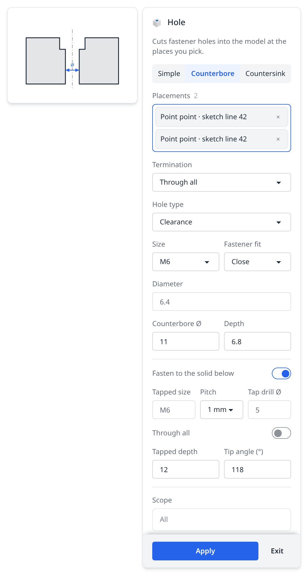
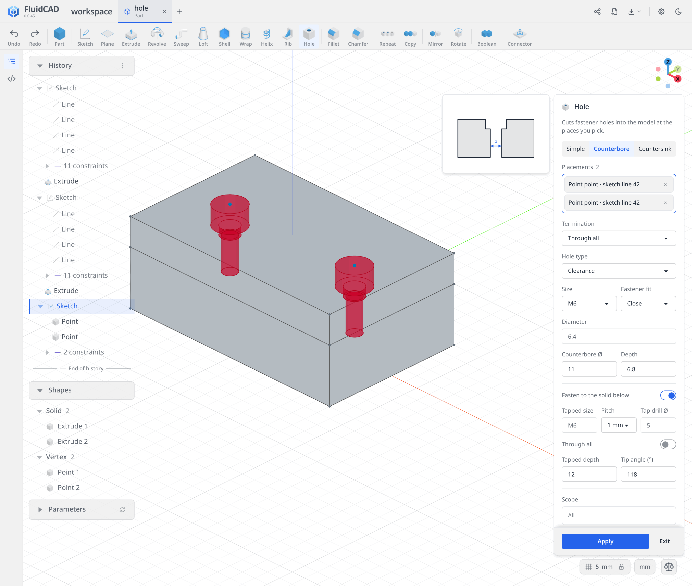
- Click Hole on the toolbar. The dialog docks on the right with its Placements slot armed, and a section drawing of the hole floats in a card to its left.
- Click where the holes go, as many places as you like. Each pick becomes a chip:
- an existing connector;
- a vertex of a sketch: a circle centre, a line end, a sketch point, or the corner of a guide. Guides are drawn over the model for as long as their sketch is shown, so a construction layout keeps its corners clickable;
- an anchor on a face or an edge. Hovering floats the anchor nearest the cursor as a translucent frame: the centre of a face, or the start, end or centre of an edge. On an arc, hover its middle for the arc's centre. Inside a part, the anchor becomes a new connector when you apply.
- Choose the entry with the Simple / Counterbore / Countersink tabs, then the Termination (Through all or Blind) and the Hole type (Drilled, Clearance or Tapped). Clearance puts Size and Fastener fit on one row, and Tapped puts Size and Pitch there. The Size list groups Metric and Imperial sizes, and the Pitch list groups Coarse and Fine. Drilled hides the row and takes the Diameter you type. The section drawing shows which dimension the field you are editing sets, and a red ghost shows the holes in the viewport.
- Optional, for a Clearance hole: turn on Fasten to the solid below, and the next solid along each hole's axis, the one the screw threads into, gets the matching tapped hole. See Fastening to another solid.
- Click Apply. The timeline gains a Hole row and the
hole()statement is written to the file.
To change a hole later, double-click its row in the timeline. The dialog reopens with every placement as a chip, and the ghost shows the holes where they are cut now.
- 1Simple / Counterbore / CountersinkThe entry of the hole. Counterbore and Countersink add their own two fields below the diameter.
- 2PlacementsWhere the holes start. Click connectors, sketch vertices (guide corners included), or face and edge anchors in 3D; click a chip's ✕ to drop it.
- 3Section drawingThe hole in section, in a card that stays in view while the dialog scrolls. The dimension of the field you are editing is drawn in colour.
- 4TerminationThrough all cuts through every solid in scope. Blind takes a Depth to the shoulder and a Tip angle (118° for a drill point, 0 for a flat bottom).
- 5Hole typeDrilled takes a Diameter you type. Clearance and Tapped read the diameter from the fastener tables, converted into the document unit.
- 6Size, Fastener fit or PitchThe fastener size, from the Metric (M3, M6 …) or Imperial (#10, 1/4 …) group. Beside it, Clearance takes the fit (Close, Normal, Loose) and Tapped the Pitch, grouped into Coarse and Fine.
- 7Fasten to the solid belowClearance holes only, and optional: the next solid along each hole's axis, the one the screw threads into, gets a tapped hole. Once it is on, the rows below it set that tapped hole.
- 8ScopeWhich solids the holes cut. All considers every solid in the scene.
The plate and its placements
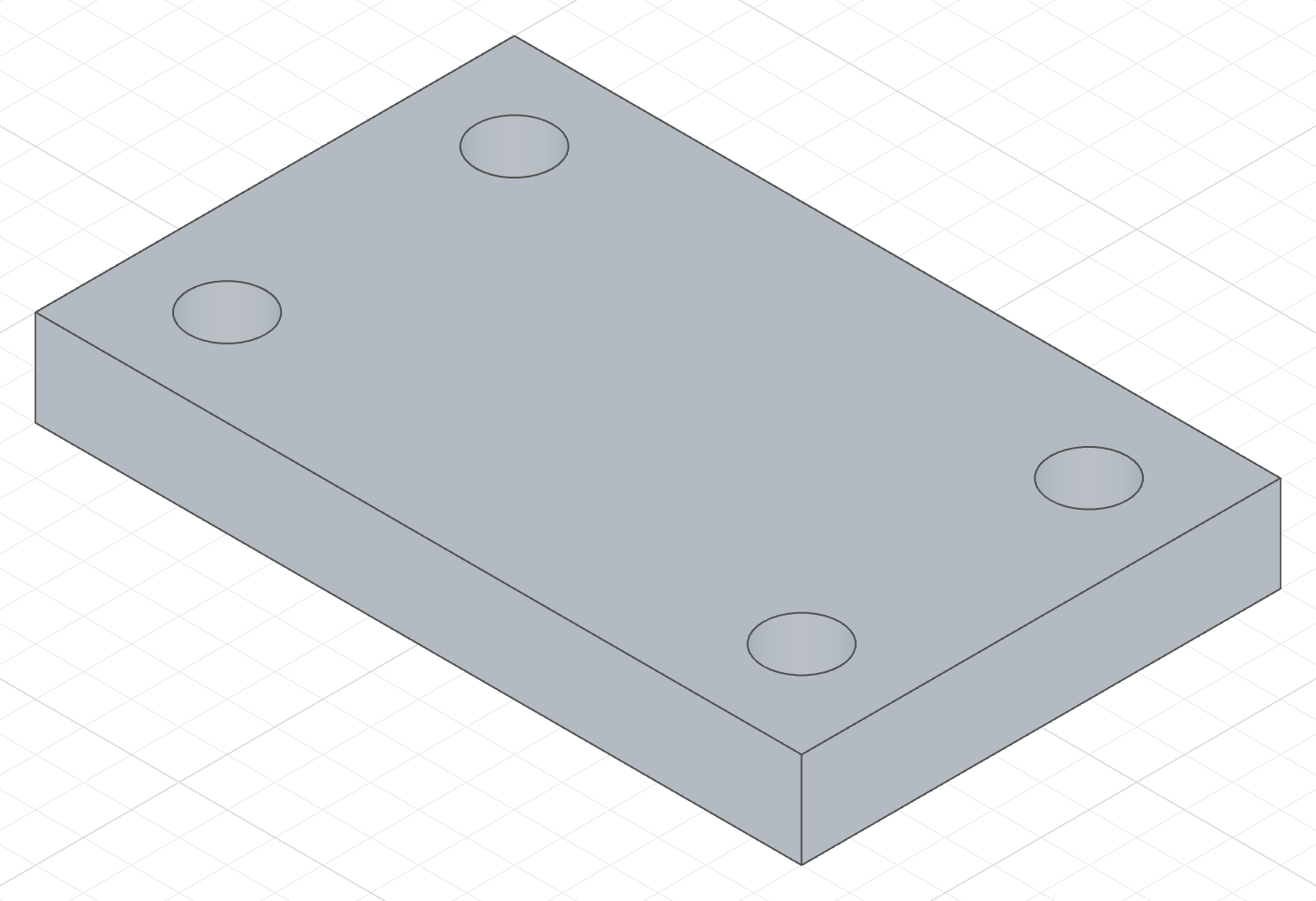
The examples below share one plate. Four sketch points on its top face mark the holes; returning them from the sketch callback names them for the hole statement (holes.geometries.p1). The dialog writes that return for you when you click a sketch vertex.
The plate and the four points
import { sketch, line, point, extrude } from 'fluidcad/core';
import { coincident, distance, fix, horizontal, vertical } from 'fluidcad/constraints';

// An 80 × 50 × 10 mounting plate. The four points on its top face are
// where the holes go: a sketch point has no edge, it only marks a place.
sketch("xy", () => {
    const b = line([-40, -25], [40, -25]);
    const r = line([40, -25], [40, 25]);
    const t = line([40, 25], [-40, 25]);
    const l = line([-40, 25], [-40, -25]);
    coincident(b.end(), r.start());
    coincident(r.end(), t.start());
    coincident(t.end(), l.start());
    coincident(l.end(), b.start());
    horizontal(b);
    vertical(r);
    horizontal(t);
    vertical(l);
    fix(b.start(), [-40, -25]);
    distance(b.start(), b.end(), 80);
    distance(r.start(), r.end(), 50);
});
const plate = extrude(10);

// Returning the points names them for statements outside the sketch:
// `holes.geometries.p1` is the first point.
const holes = sketch(plate.endFaces(), () => {
    const p1 = point([-30, -15]);
    const p2 = point([30, -15]);
    const p3 = point([30, 15]);
    const p4 = point([-30, 15]);
    fix(p1, [-30, -15]);
    fix(p2, [30, -15]);
    fix(p3, [30, 15]);
    fix(p4, [-30, 15]);
    return { p1, p2, p3, p4 };
});
Clearance holes
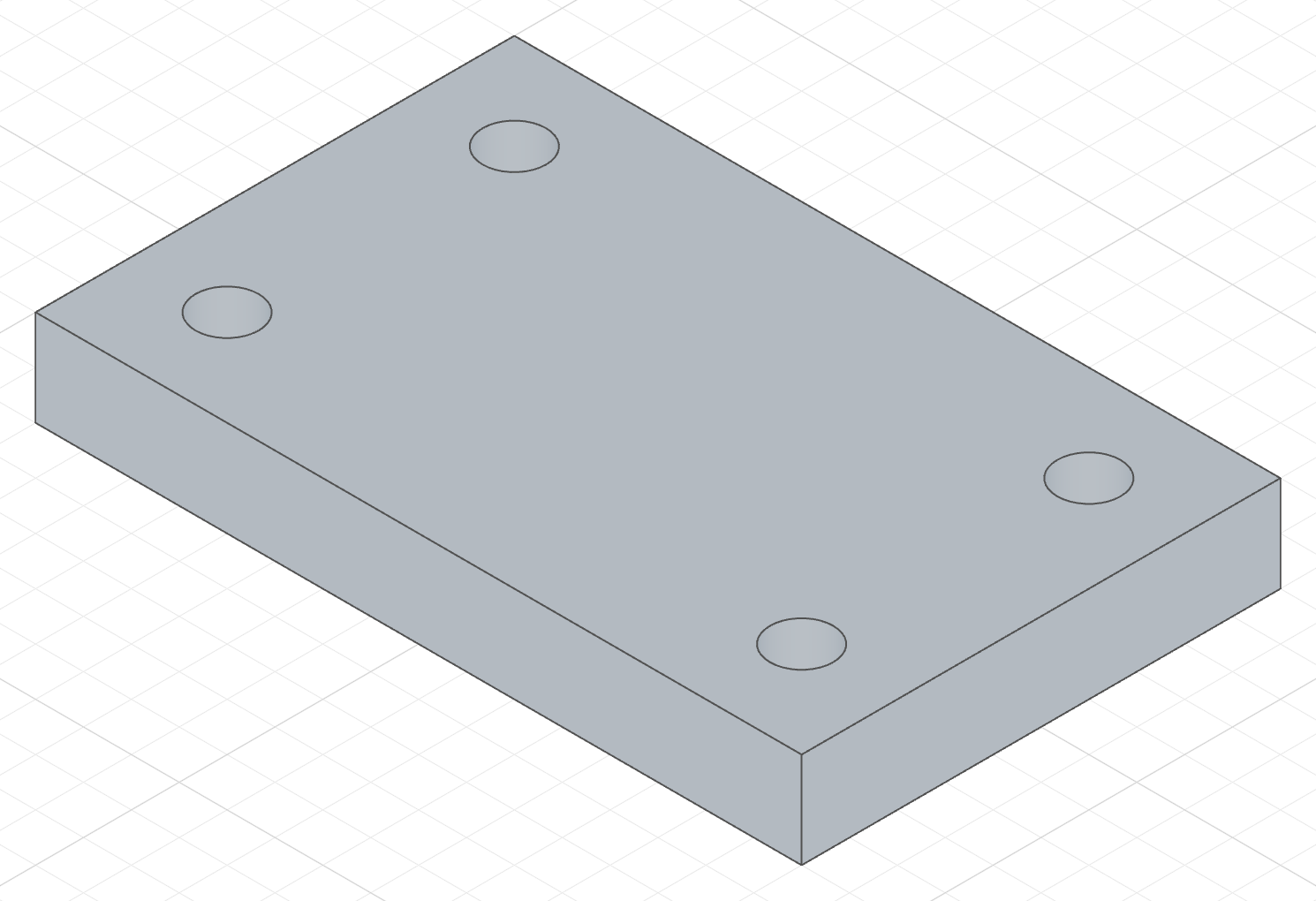
hole('M6', p1, p2, p3, p4)Four M6 clearance holes at the normal fit (Ø6.6), through the plate.
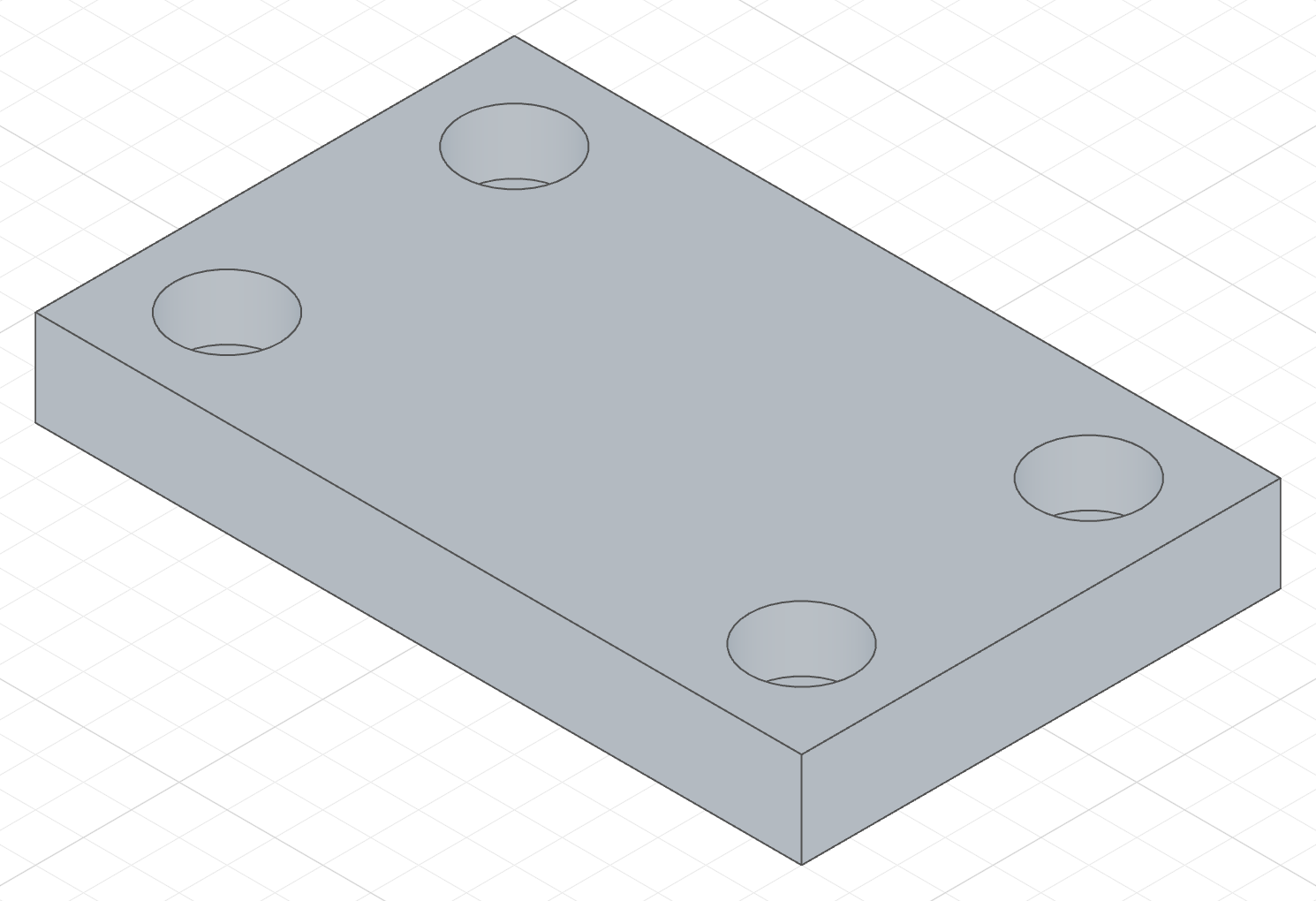
.clearance('close').counterbore()Close fit (Ø6.4) with the socket-head counterbore from the table: Ø11, 6.8 deep.
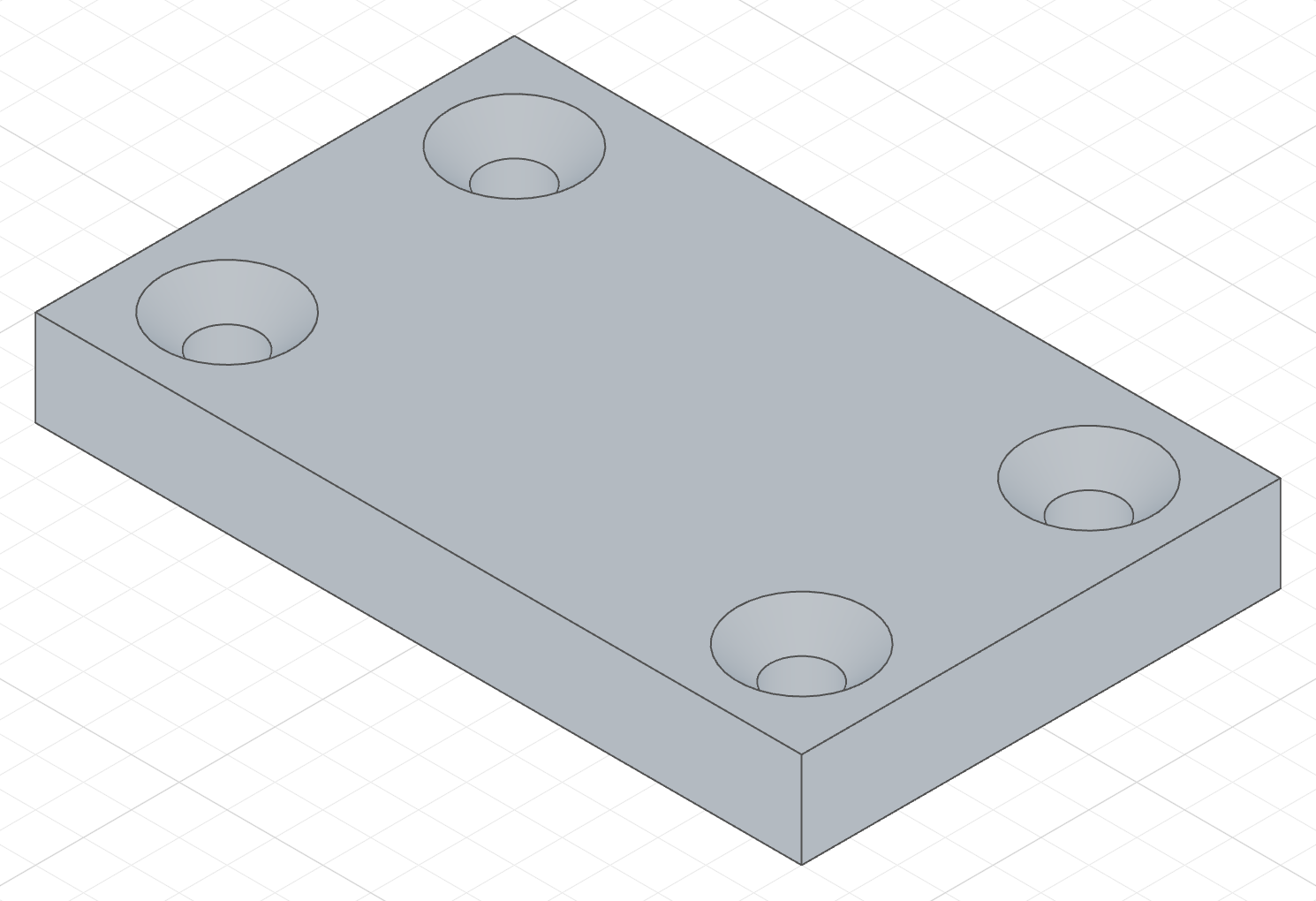
.countersink()The flat-head countersink from the table: Ø13.44 at the surface, 90°.
Simple
import { sketch, line, point, extrude, hole } from 'fluidcad/core';
import { coincident, distance, fix, horizontal, vertical } from 'fluidcad/constraints';

// An 80 × 50 × 10 mounting plate. The four points on its top face are
// where the holes go: a sketch point has no edge, it only marks a place.
sketch("xy", () => {
    const b = line([-40, -25], [40, -25]);
    const r = line([40, -25], [40, 25]);
    const t = line([40, 25], [-40, 25]);
    const l = line([-40, 25], [-40, -25]);
    coincident(b.end(), r.start());
    coincident(r.end(), t.start());
    coincident(t.end(), l.start());
    coincident(l.end(), b.start());
    horizontal(b);
    vertical(r);
    horizontal(t);
    vertical(l);
    fix(b.start(), [-40, -25]);
    distance(b.start(), b.end(), 80);
    distance(r.start(), r.end(), 50);
});
const plate = extrude(10);

// Returning the points names them for statements outside the sketch:
// `holes.geometries.p1` is the first point.
const holes = sketch(plate.endFaces(), () => {
    const p1 = point([-30, -15]);
    const p2 = point([30, -15]);
    const p3 = point([30, 15]);
    const p4 = point([-30, 15]);
    fix(p1, [-30, -15]);
    fix(p2, [30, -15]);
    fix(p3, [30, 15]);
    fix(p4, [-30, 15]);
    return { p1, p2, p3, p4 };
});

// Four M6 clearance holes (normal fit, Ø6.6), through the whole plate.
hole('M6', holes.geometries.p1, holes.geometries.p2, holes.geometries.p3, holes.geometries.p4);
Counterbore
import { sketch, line, point, extrude, hole } from 'fluidcad/core';
import { coincident, distance, fix, horizontal, vertical } from 'fluidcad/constraints';

// An 80 × 50 × 10 mounting plate. The four points on its top face are
// where the holes go: a sketch point has no edge, it only marks a place.
sketch("xy", () => {
    const b = line([-40, -25], [40, -25]);
    const r = line([40, -25], [40, 25]);
    const t = line([40, 25], [-40, 25]);
    const l = line([-40, 25], [-40, -25]);
    coincident(b.end(), r.start());
    coincident(r.end(), t.start());
    coincident(t.end(), l.start());
    coincident(l.end(), b.start());
    horizontal(b);
    vertical(r);
    horizontal(t);
    vertical(l);
    fix(b.start(), [-40, -25]);
    distance(b.start(), b.end(), 80);
    distance(r.start(), r.end(), 50);
});
const plate = extrude(10);

// Returning the points names them for statements outside the sketch:
// `holes.geometries.p1` is the first point.
const holes = sketch(plate.endFaces(), () => {
    const p1 = point([-30, -15]);
    const p2 = point([30, -15]);
    const p3 = point([30, 15]);
    const p4 = point([-30, 15]);
    fix(p1, [-30, -15]);
    fix(p2, [30, -15]);
    fix(p3, [30, 15]);
    fix(p4, [-30, 15]);
    return { p1, p2, p3, p4 };
});

// Close-fit M6 holes with the socket-head counterbore from the table
// (Ø11, 6.8 deep). Pass numbers to override: .counterbore(12, 7).
hole('M6', holes.geometries.p1, holes.geometries.p2, holes.geometries.p3, holes.geometries.p4)
    .clearance('close')
    .counterbore();
Countersink
import { sketch, line, point, extrude, hole } from 'fluidcad/core';
import { coincident, distance, fix, horizontal, vertical } from 'fluidcad/constraints';

// An 80 × 50 × 10 mounting plate. The four points on its top face are
// where the holes go: a sketch point has no edge, it only marks a place.
sketch("xy", () => {
    const b = line([-40, -25], [40, -25]);
    const r = line([40, -25], [40, 25]);
    const t = line([40, 25], [-40, 25]);
    const l = line([-40, 25], [-40, -25]);
    coincident(b.end(), r.start());
    coincident(r.end(), t.start());
    coincident(t.end(), l.start());
    coincident(l.end(), b.start());
    horizontal(b);
    vertical(r);
    horizontal(t);
    vertical(l);
    fix(b.start(), [-40, -25]);
    distance(b.start(), b.end(), 80);
    distance(r.start(), r.end(), 50);
});
const plate = extrude(10);

// Returning the points names them for statements outside the sketch:
// `holes.geometries.p1` is the first point.
const holes = sketch(plate.endFaces(), () => {
    const p1 = point([-30, -15]);
    const p2 = point([30, -15]);
    const p3 = point([30, 15]);
    const p4 = point([-30, 15]);
    fix(p1, [-30, -15]);
    fix(p2, [30, -15]);
    fix(p3, [30, 15]);
    fix(p4, [-30, 15]);
    return { p1, p2, p3, p4 };
});

// M6 holes with the flat-head countersink from the table (Ø13.44, 90°).
hole('M6', holes.geometries.p1, holes.geometries.p2, holes.geometries.p3, holes.geometries.p4)
    .countersink();
A string size ('M6', '1/4', '#10') reads the fastener tables. Without a chain it is a normal-fit clearance hole; .clearance('close' | 'normal' | 'loose') picks the fit. .counterbore() and .countersink() with no values take the table entry for that size; pass numbers to override them: .counterbore(12, 7), .countersink(14, 82). Metric tables are in millimetres and inch tables in inches; the values are converted into the file's unit.
Drilled and blind holes
A numeric size is a drilled hole of that diameter; it has no table, so a counterbore or countersink on it needs explicit values. Blind stops the hole at a depth measured from the surface to the shoulder; the tip angle adds a drill point below it. In the dialog a tip angle of 0 leaves a flat bottom; in code, leave the second argument out: .depth(6).
The code behind it
import { sketch, line, point, extrude, hole } from 'fluidcad/core';
import { coincident, distance, fix, horizontal, vertical } from 'fluidcad/constraints';

// An 80 × 50 × 10 mounting plate. The four points on its top face are
// where the holes go: a sketch point has no edge, it only marks a place.
sketch("xy", () => {
    const b = line([-40, -25], [40, -25]);
    const r = line([40, -25], [40, 25]);
    const t = line([40, 25], [-40, 25]);
    const l = line([-40, 25], [-40, -25]);
    coincident(b.end(), r.start());
    coincident(r.end(), t.start());
    coincident(t.end(), l.start());
    coincident(l.end(), b.start());
    horizontal(b);
    vertical(r);
    horizontal(t);
    vertical(l);
    fix(b.start(), [-40, -25]);
    distance(b.start(), b.end(), 80);
    distance(r.start(), r.end(), 50);
});
const plate = extrude(10);

// Returning the points names them for statements outside the sketch:
// `holes.geometries.p1` is the first point.
const holes = sketch(plate.endFaces(), () => {
    const p1 = point([-30, -15]);
    const p2 = point([30, -15]);
    const p3 = point([30, 15]);
    const p4 = point([-30, 15]);
    fix(p1, [-30, -15]);
    fix(p2, [30, -15]);
    fix(p3, [30, 15]);
    fix(p4, [-30, 15]);
    return { p1, p2, p3, p4 };
});

// Drilled Ø8, blind: 6 deep to the shoulder, with a 118° drill point below.
hole(8, holes.geometries.p1, holes.geometries.p2, holes.geometries.p3, holes.geometries.p4)
    .depth(6, 118);
Tapped holes
.tapped() cuts the hole at the tap-drill diameter for the size: the coarse pitch by default, or a pitch you name (.tapped(0.75) for M6 fine; threads per inch for inch sizes). Threads themselves are not modelled yet; the size and pitch stay in the statement for a later thread feature.
hole('M6', p1).tapped()                    // Ø5.0, for M6 × 1
hole('M8', p2).tapped(1).depth(10, 118)    // Ø7.0, for M8 × 1, blind with a drill point
Fastening to another solid
A screw passes through one solid and threads into the next. That normally takes two holes: a clearance hole in the first solid and a tapped hole in the second. With Fasten to the solid below you model only the clearance hole. The next solid along the hole's axis, the one under the solid the hole sits on, gets the matching tapped hole on the same axis, cut at the tap-drill diameter for the same fastener size. You never name that solid. For M6 that is Ø6.6 through the cover and Ø5 in the base.
The pictures below show the rear half of a joint, an 8 mm cover on a 20 mm base, so both bores are visible in section.
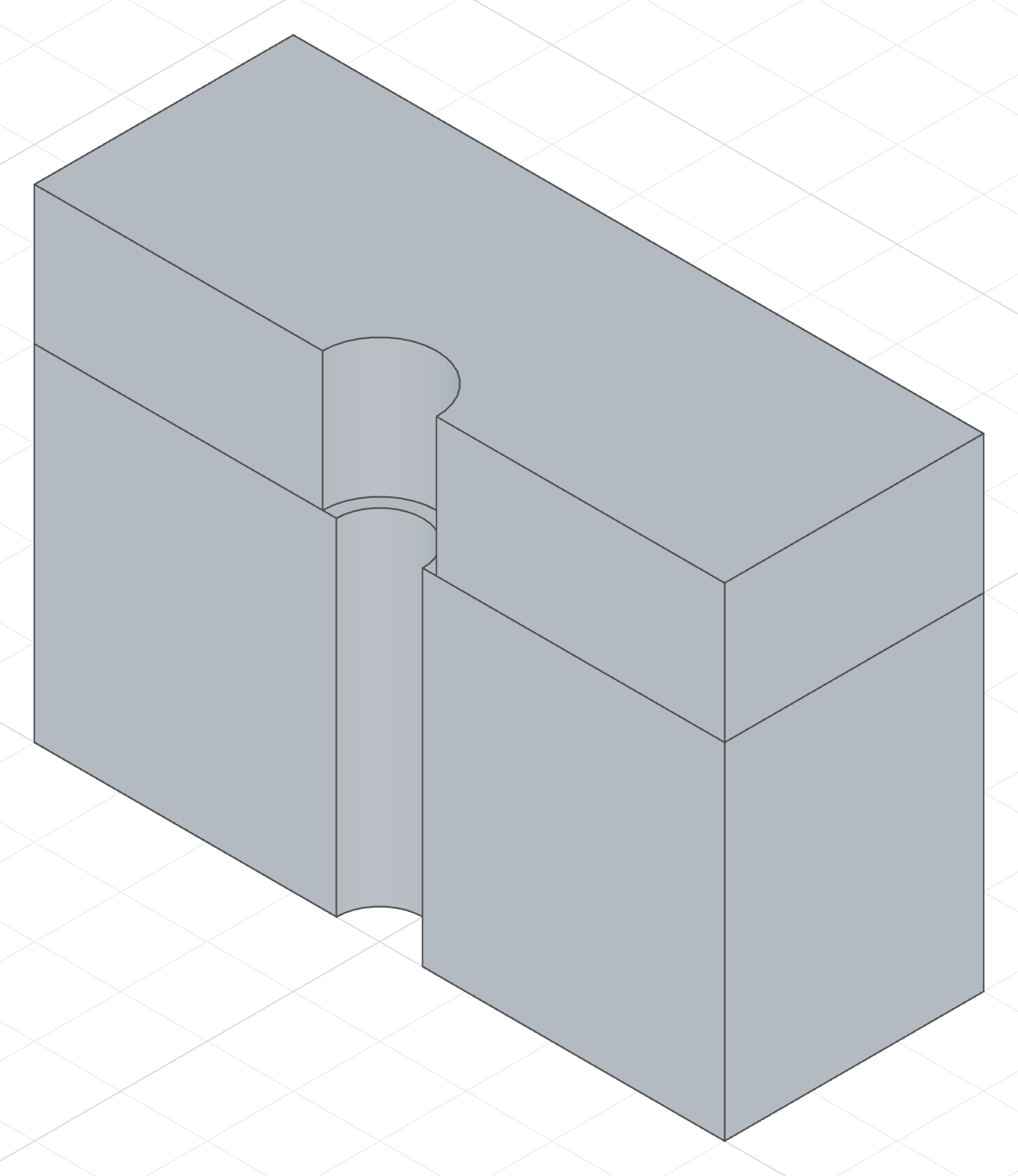
.fasten()Ø6.6 through the cover, Ø5 through the whole base.
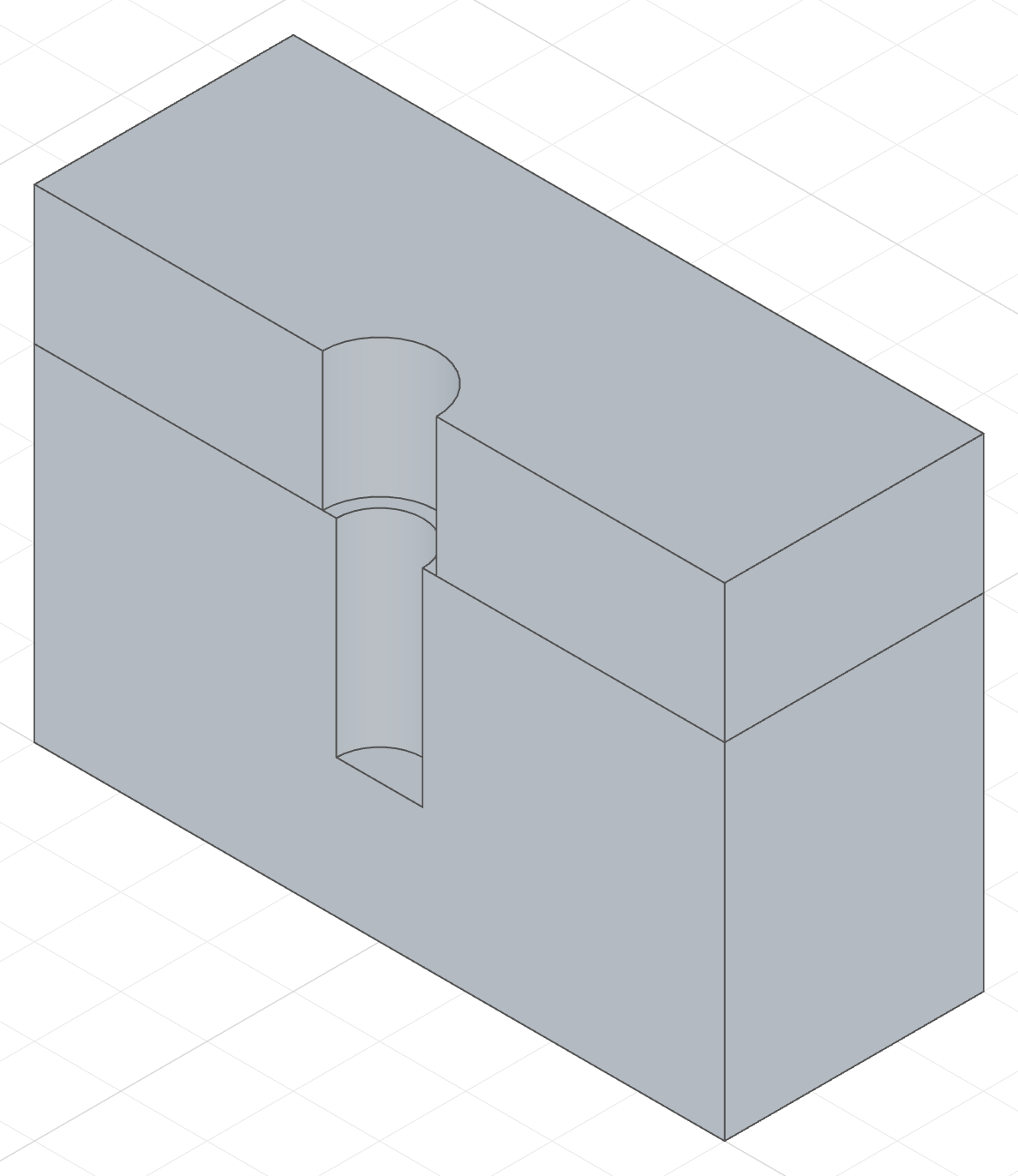
.fasten('coarse', 12)The tapped hole stops 12 below the top face of the base, with a flat bottom.
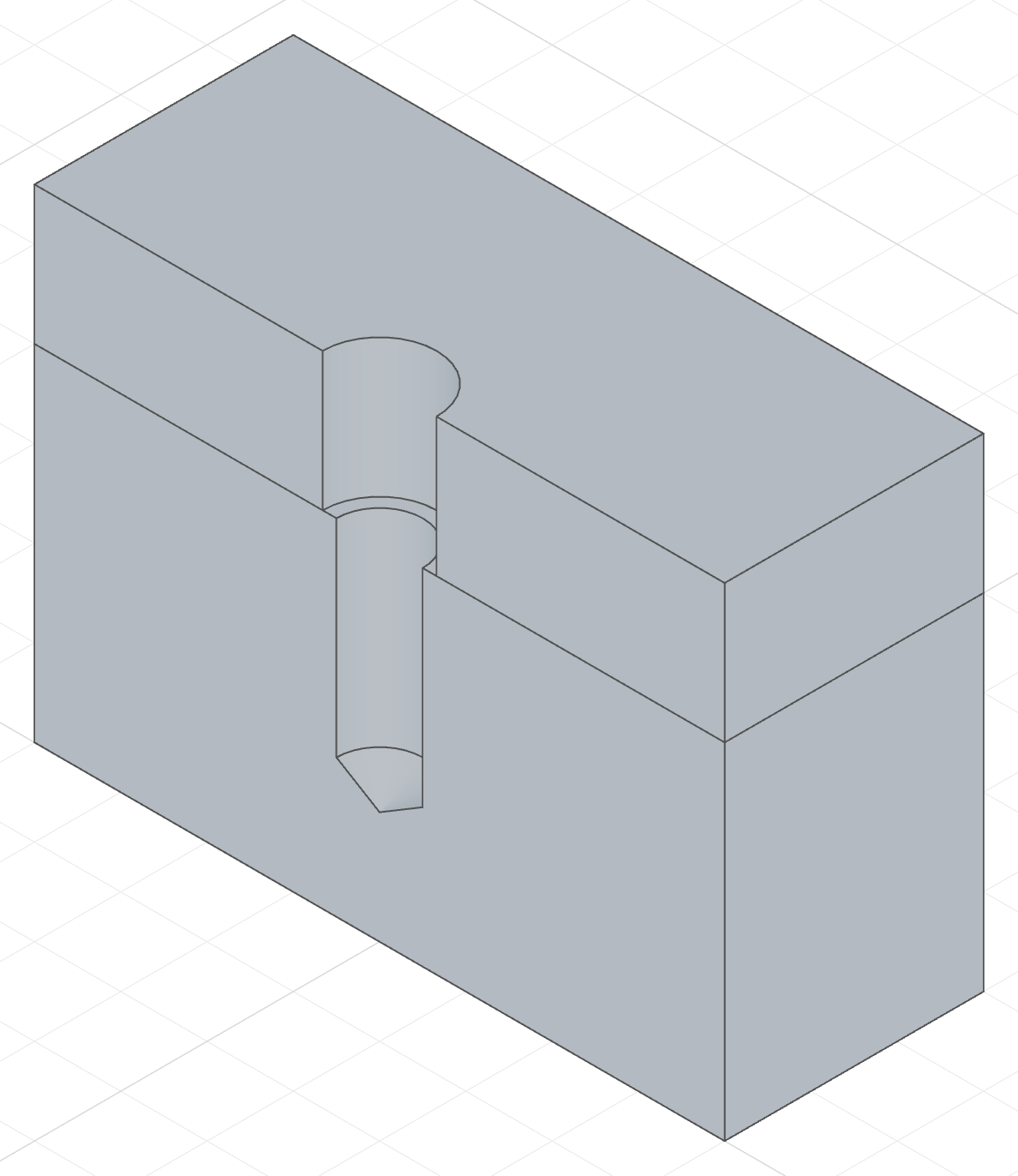
.fasten('coarse', 12, 118)12 deep to the shoulder, then the 118° point of a standard drill.
In the dialog
- Set Hole type to Clearance. The Fasten to the solid below toggle appears above Scope. It is hidden for Drilled and Tapped holes.
- Turn the toggle on. The red ghost now shows both bores at each placement: the clearance hole through the solid the hole sits on, and the narrower tapped hole in the solid under it.
- Three fields appear under the toggle. Tapped size and Tap drill Ø are read-only: they follow Size. Pitch starts at the coarse pitch for the size; pick a fine pitch if you need one.
- Through all is on, so the tapped hole runs through the whole fastened solid. Turn it off for a blind hole: type the Tapped depth, and a Tip angle (118 by default, 0 for a flat bottom).
In code
.fasten() takes no solid, only three optional values: the pitch, the blind depth and the tip angle.
hole('M6', p).fasten()                      // Ø5 through the whole base (M6 × 1, the coarse pitch)
hole('M6', p).fasten(0.75)                  // Ø5.25, for M6 × 0.75 fine
hole('M6', p).fasten('coarse', 12)          // coarse pitch, blind: 12 deep, flat bottom
hole('M6', p).fasten('coarse', 12, 118)     // blind, with a 118° drill point below the 12
- The fastened solid is found along each hole's axis: the first solid the axis enters past the ones the clearance hole cuts. Here the clearance hole cuts the cover, so the base under it is tapped.
- The pitch is in millimetres for a metric size and in threads per inch for an inch size. Leave it out for the coarse pitch. Write
'coarse'when a depth follows, so the pitch keeps following the size. - The depth is measured from the face where the hole axis enters the fastened solid, not from the placement. In the pictures above, 12 is counted from the top of the base, which is 8 below the placement on top of the 8 mm cover. Leave it out and the tapped hole runs through the whole solid.
- The tip angle is the included angle of the drill point below the depth: 118 for a standard drill. Leave it out for a flat bottom. It needs a depth, because a through hole has no drill point.
Through the fastened solid
import { sketch, line, point, extrude, hole } from 'fluidcad/core';
import { coincident, distance, fix, horizontal, vertical } from 'fluidcad/constraints';

// A base block, 40 × 15 and 20 thick: the solid the screw threads into.
// Both blocks here are the rear half of a joint: their front face runs
// through the hole axis, so the picture shows the two bores in section.
sketch("xy", () => {
    const b = line([-20, 0], [20, 0]);
    const r = line([20, 0], [20, 15]);
    const t = line([20, 15], [-20, 15]);
    const l = line([-20, 15], [-20, 0]);
    coincident(b.end(), r.start());
    coincident(r.end(), t.start());
    coincident(t.end(), l.start());
    coincident(l.end(), b.start());
    horizontal(b);
    vertical(r);
    horizontal(t);
    vertical(l);
    fix(b.start(), [-20, 0]);
    distance(b.start(), b.end(), 40);
    distance(r.start(), r.end(), 15);
});
const base = extrude(20);

// An 8 mm cover on top of the base. `.new()` keeps it a solid of its own.
sketch(base.endFaces(), () => {
    const b = line([-20, 0], [20, 0]);
    const r = line([20, 0], [20, 15]);
    const t = line([20, 15], [-20, 15]);
    const l = line([-20, 15], [-20, 0]);
    coincident(b.end(), r.start());
    coincident(r.end(), t.start());
    coincident(t.end(), l.start());
    coincident(l.end(), b.start());
    horizontal(b);
    vertical(r);
    horizontal(t);
    vertical(l);
    fix(b.start(), [-20, 0]);
    distance(b.start(), b.end(), 40);
    distance(r.start(), r.end(), 15);
});
const cover = extrude(8).new();

// One point on the cover's top face marks the screw.
const seat = sketch(cover.endFaces(), () => {
    const p = point([0, 0]);
    fix(p, [0, 0]);
    return { p };
});

// One statement, two holes. The cover takes the M6 clearance hole (Ø6.6).
// The base under it, the next solid along the hole axis, takes the M6
// tapped hole: Ø5, the tap drill for M6 × 1, through the whole block.
hole('M6', seat.geometries.p).fasten();
Blind, with a drill point
import { sketch, line, point, extrude, hole } from 'fluidcad/core';
import { coincident, distance, fix, horizontal, vertical } from 'fluidcad/constraints';

// A base block, 40 × 15 and 20 thick: the solid the screw threads into.
// Both blocks here are the rear half of a joint: their front face runs
// through the hole axis, so the picture shows the two bores in section.
sketch("xy", () => {
    const b = line([-20, 0], [20, 0]);
    const r = line([20, 0], [20, 15]);
    const t = line([20, 15], [-20, 15]);
    const l = line([-20, 15], [-20, 0]);
    coincident(b.end(), r.start());
    coincident(r.end(), t.start());
    coincident(t.end(), l.start());
    coincident(l.end(), b.start());
    horizontal(b);
    vertical(r);
    horizontal(t);
    vertical(l);
    fix(b.start(), [-20, 0]);
    distance(b.start(), b.end(), 40);
    distance(r.start(), r.end(), 15);
});
const base = extrude(20);

// An 8 mm cover on top of the base. `.new()` keeps it a solid of its own.
sketch(base.endFaces(), () => {
    const b = line([-20, 0], [20, 0]);
    const r = line([20, 0], [20, 15]);
    const t = line([20, 15], [-20, 15]);
    const l = line([-20, 15], [-20, 0]);
    coincident(b.end(), r.start());
    coincident(r.end(), t.start());
    coincident(t.end(), l.start());
    coincident(l.end(), b.start());
    horizontal(b);
    vertical(r);
    horizontal(t);
    vertical(l);
    fix(b.start(), [-20, 0]);
    distance(b.start(), b.end(), 40);
    distance(r.start(), r.end(), 15);
});
const cover = extrude(8).new();

// One point on the cover's top face marks the screw.
const seat = sketch(cover.endFaces(), () => {
    const p = point([0, 0]);
    fix(p, [0, 0]);
    return { p };
});

// The tapped hole is 12 deep to the shoulder, measured from the base's top
// face, with the 118° point of a standard drill below it. 'coarse' in the
// pitch position keeps the coarse pitch for the size.
hole('M6', seat.geometries.p).fasten('coarse', 12, 118);
.fasten() comes after the entry and the depth of the clearance hole, and before .scope(). This is the order the dialog writes:
hole('M6', p).clearance('close').counterbore().fasten('coarse', 12, 118).scope(cover);
What is cut, and what is not
- With no scope set, the clearance hole cuts only the solid the hole sits on, the first solid its axis enters, and the tapped hole goes into the next one. With
.scope(), the clearance hole cuts the scoped solids, and the tapped hole goes into the first solid past them along the axis. A scoped solid never takes the tapped hole. - Each placement taps the solid under its own axis, so one statement can fasten a cover to two different blocks, and a mirrored or repeated fastened hole taps the solid under each copy.
- The tapped hole opens on the face where the hole axis enters that solid. If no solid lies past the clearance hole along the axis, the hole reports an error and cuts nothing.
- Only a clearance hole of a fastener size can fasten:
'M6','1/4', with or without.clearance(). A drilled hole (hole(6, p)) and a.tapped()hole cannot. - Threads are not modelled, the same as for
.tapped(). The tapped hole is a plain bore at the tap-drill diameter.
Holes on construction lines
A guide never becomes part of a profile, and it stays drawn over the model once its sketch is finished, for as long as the sketch is shown. A hole hides the sketch it is placed on, like any other feature that uses a sketch, and the guides go with it: click the eye on the sketch's row in the History panel to show it again, and its points are clickable like those of any sketch on screen. The ends of a guide's lines are clickable in the dialog, so a construction layout can position a whole pattern: dimension a guide rectangle once, then click its corners. Each corner is written as the end of one of the lines (layout.geometries.b.start()). A corner two lines share names the line that comes first in the sketch.
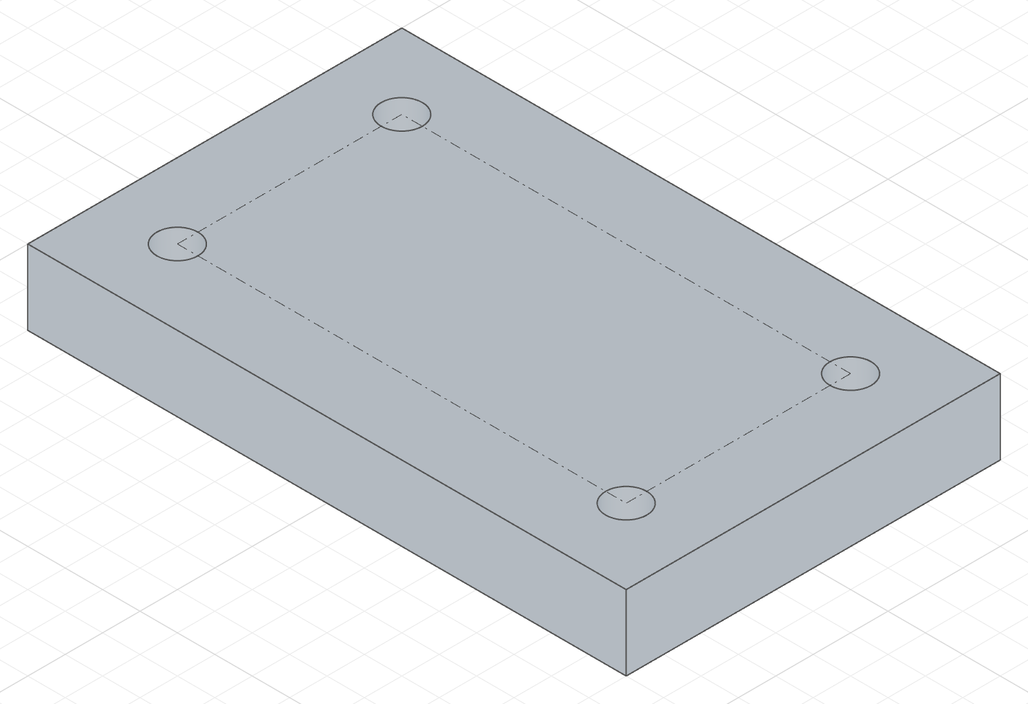
The code behind it
import { sketch, line, extrude, hole } from 'fluidcad/core';
import { coincident, distance, fix, horizontal, vertical } from 'fluidcad/constraints';

// The same 80 × 50 × 10 mounting plate.
sketch("xy", () => {
    const b = line([-40, -25], [40, -25]);
    const r = line([40, -25], [40, 25]);
    const t = line([40, 25], [-40, 25]);
    const l = line([-40, 25], [-40, -25]);
    coincident(b.end(), r.start());
    coincident(r.end(), t.start());
    coincident(t.end(), l.start());
    coincident(l.end(), b.start());
    horizontal(b);
    vertical(r);
    horizontal(t);
    vertical(l);
    fix(b.start(), [-40, -25]);
    distance(b.start(), b.end(), 80);
    distance(r.start(), r.end(), 50);
});
const plate = extrude(10);

// A 60 × 30 construction rectangle on the top face lays out the holes.
// Guides never become a profile, and they stay drawn over the model
// while the sketch is shown, so their corners can be clicked.
const layout = sketch(plate.endFaces(), () => {
    const b = line([-30, -15], [30, -15]).guide();
    const r = line([30, -15], [30, 15]).guide();
    const t = line([30, 15], [-30, 15]).guide();
    const l = line([-30, 15], [-30, -15]).guide();
    coincident(b.end(), r.start());
    coincident(r.end(), t.start());
    coincident(t.end(), l.start());
    coincident(l.end(), b.start());
    horizontal(b);
    vertical(r);
    horizontal(t);
    vertical(l);
    fix(b.start(), [-30, -15]);
    distance(b.start(), b.end(), 60);
    distance(r.start(), r.end(), 30);
    return { b, t };
});

// An M5 clearance hole on each corner: both ends of the bottom and top lines.
hole('M5',
    layout.geometries.b.start(), layout.geometries.b.end(),
    layout.geometries.t.start(), layout.geometries.t.end());
Holes at connectors
Inside a part, a hole can start at a connector. A connector's Z points out of the face it sits on, so the hole drills against it, into the material, and the same connector later mates the bolt in an assembly. Repeat the hole to make a bolt circle:
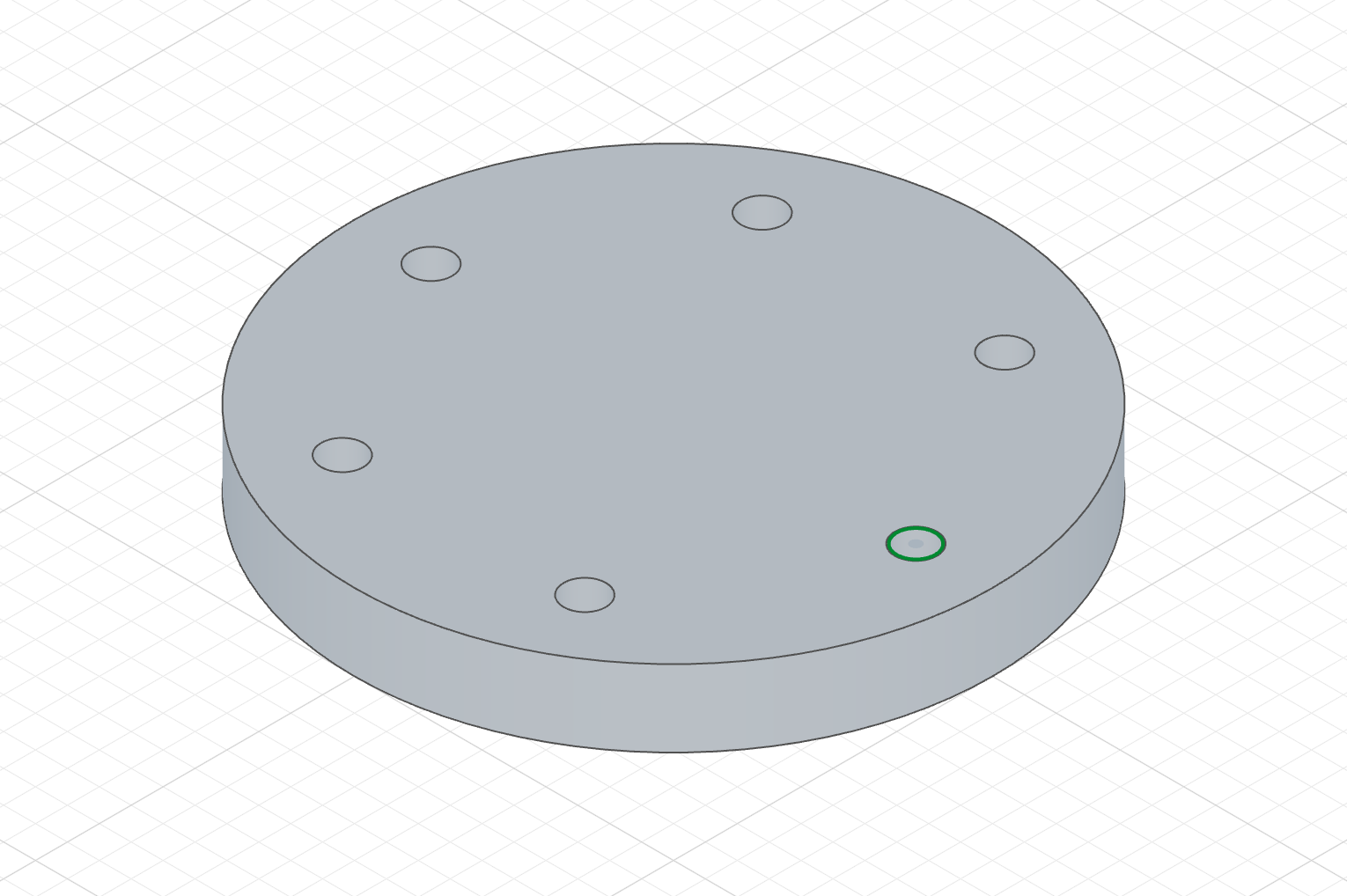
The code behind it
import { part, sketch, circle, extrude, connector, hole, repeat } from 'fluidcad/core';
import { fix, diameter } from 'fluidcad/constraints';

// A flange: a 100 mm disc, 12 thick. One connector on the top face is the
// bolt seat; the hole is cut at it and then repeated around the axis.
part('Flange', () => {
    sketch("xy", () => {
        const rim = circle([0, 0], 100);
        fix(rim.center(), [0, 0]);
        diameter(rim, 100);
    });
    const disc = extrude(12);

    // The bolt seat: a connector at the centre of a small circle drawn on
    // the top face. Its Z points out of the face, so the hole drills in.
    const seat = sketch(disc.endFaces(), () => {
        const c = circle([38, 0], 6);
        fix(c.center(), [38, 0]);
        diameter(c, 6);
        return { c };
    });
    const bolt = connector('bolt', seat.geometries.c.center());

    // An M6 clearance hole at the connector, then five more around the axis.
    // The repeat takes the hole (the last feature); the connector stays put.
    hole('M6', bolt).clearance('normal');
    repeat('circular', 'z', { count: 6, angle: 360 });
});
When you pick a face or edge anchor in the dialog inside a part, Apply writes a connector at that anchor and places the hole on it. Outside a part the hole takes the anchor expression directly: hole(6, e.endFaces().center()).
Removing a hole from the History panel removes the connectors it was placed at with it. A connector something else still uses stays: another hole, a copy(), or a mate in an assembly that reads it as instance.connectors.name.
Direction, scope and selection
- A hole drills opposite the placement's normal: into the face a sketch sits on, or against a connector's Z. To drill the other way from a connector, turn the connector around:
.rotate('x', 180). - By default a hole cuts every solid in the scene;
.scope(plate)narrows it, as in the other dialogs. A fastened hole cuts less: its clearance hole cuts the solid it sits on (or the scoped solids), and its tapped hole only the next solid along the axis. - The cut geometry is selectable:
h.faces()are the walls,h.edges()every rim,h.startEdges()the rims on the entry face andh.endEdges()the floor rims of a blind hole or the exit rims of a through hole. On a hole with.fasten(), each list holds the clearance holes' geometry first and the tapped holes' after.
const h = hole('M6', p1).counterbore();
chamfer(0.5, h.startEdges());